820" Rev. B SUPERSEDES Rw.A Thii manualcontainsimportantWarnings and Insuuctions. Read the rnanua! and keep it for rsference. 1 HP, Portable, Electric . . LTIMATE AIRLESS PAINT SPRAYER Model W,Series A Less hdse,.gun. and filter SzW psi (210 bad MAXIMUM WORKING PRESSURE Index ......................... ....................... ......................... .................. ............. ............................. .................. ....................... .......... ................................ .
nerd Safe equlpment%nerates very high fluid pressure. Sprayfrom thegun,leaksorrupturedcomponents can inject fluid through your skin and into your body and cause extremely serious bodily injury,including the need for amputation. Also, fluid injectedorsplashed into the eyes can cause'serious damage. %IS NEVER poim the spray gun at anyone or at any paq of the body. NEVER put hand or fingers over the spray tip. NEVER try to "blow back" paint; this is NOT an air spray system.
GEtPed $Pf&Y . . . . , Static electricity is created by the high velocity flow of fluid through the pump and hose. If every partof the spray equipment is not properly grounded, sparking m y occur, and the systemmaybecomehazardous.Sparkingmayalsooccur when plugging in or unplugging a power supply cord. Sparks can ignite fumes from solvents end the fluid being sprayed, dust panicles and other flammable wbstances;whether you are spraying indoors or outdoors, and.
Coutsignes g6n6ralm de securite Cet appareii produit un fluida B trh haute pression. LB fluide pulv4risti parle pistoiet ou ie fluide sous pression pmvenant de fuiies ou de ruptures peut p B n h r sous ia peau ou B I'intBrieur du corps et entraher des blessurest d s graves, voir mBme une amputation. MCma sansW e sous pression. ie fluide Bclaboussant ou entrant dans. les yauxpautaussientrainerdes blessures graves. NE JAMAIS pointer ie pistoiet vars quelqu'un ou vers une partie quelconque du corps.
R!SWfES EN CAS DE ~ A U ~ ~ UUULUSAUOON n $ E DU MAUERjEk Cmsignes g6n6uales $0 sQcuritpB . . . . Puessi n PRESSION MAXIMUM DE Toute utiiisation,anormale de I'appareil de pulvBrisation ou des Ce pulvfrisateur peut produire une TRAVAIL 210 bar f3cX7V Ib/po.2). Sassurerque tous les aaessoires domrne, per example, ia mise sous une pression excessive.
Seeguridad general Este equipogeneraunfluidoaunapresi6nmuy alta. 0 Aparatos de seiuridad de r Ia pi5tOl~3pulverized& Asegurar que todos i o s aparatos protectores de la pistola estsn funcionandobienantesdecadauso. No scar ni rociado de la pistola. 10s escapes de fluido o roturas de los wmponentes pueden inyectar fluido en la piel y el cuerpo y causar lesiones earemadamente graves, incluyendo a veces la necesidad de amputaci6n. Tambih. el fluidoinyectado o salpicado en 10s ojos puede causar graves daflos.
.~. PELhGRO POR MAL U S 0 DEL EQUPO PBBGW6 DE 8NCENDlO 8 EXPLO$lOM segws~dedgpwasal El flub a alta velocidad del Ruido al .pasar por la bomba y Cualquler mal us0 de( equipo pulverizadoro 10s accesorios. tal como ~brepresurizaci6n. modificaci6nde piezb, UM de matenales y pmductos quimicos incompatibles, o utiliuaci6n depiezasdaiiadas o desgastadas,puedehacenqueserompan y causenlainyecci6ndefluido u otraslesionescorporales graves, incendio, explosi6n o daiion a la propiedad.
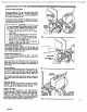
Connect Hose end.Gun Connect at least 50 . f t (15 m) hose to the fluid outlet of the pressure control. See Fig 1. Connect a spray gun to of the hose. Don't use thread sealant, and the other end don't install the spray tip yet! For two gun hookup, remove the plastic cap plugfrom ball valve and connect an accessory the secondary hose hose and spray gun. See Fig 1. CAUTION To avoid damaging the pressure control, which may result in poor equipment performance and component damage, follow these precautions: 1.
____ ._.... -..,, ~~~~~ ~ , , ~ ,.., ..~. ,,...~,,, ...*i,~~,"~-,.L. ..... ._. .ll.,..,) . . ,_","-mid ...................................................... ".LX&& ~~ ~ ~ . ~ ~ ~ '.~. . ..-.-~ - ~ 1_..L ~ Priming the Sprayer Cleaning a Clogged Tip Close the main drain valve and the secondary ball valve. See Fig 2. Plug in the sprayer. Don't install thespray tip in the gun yet1 - -. .. Place the suction tube into the paint container.
When to Flush 1. New Sprayer. YournewUltimateNovaTM lo00 Sprayerwas factow. tested in No. 10 motor oil which was left in to protect pump parts. Before using wafer-base palnt, flush with mineral spirits, followed by soapy water, and then a clean water flush. Before uslng oibbase palnt, flushwithmineral spirits only. 2. Changing Colors. flush with a compatible solvent such as mineral spirits or water. 3. Changingfrom water-base t o oll-basepaint. flush with soapy.water, then mineral spirits. 4.
- ~. ,TROUBLESHOOTING GUIDE ~~~~U~~ ... 1. 2. 3. 4. 5. 6. Engage the gunsafetylatch. Turn the ONIOFF switchto OFF. Unplug the powersupplycord. Disengagethegunsafetylatch. Hold a metal part of the gun firmly to the side of a metal pail, and trigger the gun to relieve pressure. Engagethegunsafetylatch. 8. Leave the drain valve open until you are ready to spray again. BasicMechanicalProblems 1. Check for fmzenor hadened material in the 1. Thaw'.Plug in sprayerand turn on.
refer to *is colu~ HOTOR WONTOPERATE Iiagnosing circuit board inIicator lamps. The normal andition is red lamp on, $ear lamp on when board elling pump to run. 1. Check leads from bridae 1 3 0 8 1 to motor to be 1. Replace any loose terminals and crimp to leads.Besuremaleterminalbladesare sure they are securelyjastened and properl)I mated. straight and firmly connected to mating pa I 2. Check G1 and 62 connections between cir- 2. Clean circuit board male terminals. Replacl loose or damaged terminals.
WHAT TO CHECK If check is OK, go to next check :ontiition B Continued) 6. Check motor thermal cutout switch. Connect volt meter to TP6 female and TP9 female. Plug in and turn on sprayer. Meter should read 105 to 125 VAC. Turn off and unplug sprayer. 6. Allow motor to cool. Correct cause of ove heating. If switch remains open after motc cools, check continuity W e e n TW fama and TPlO with ohmmeter. if open, replacs motor. 7. Check microswitch 1301). Reconnect TP6 7. Clean microswitch male terminals.
WHAT ro DO WHAT TO CHECK If check is OK. go to next check When checkIs not OK refer to this colul 1. Check for worn spray tip. 1. Follow Pressure Relief Procedure then replace tip. See your separate gun or tip manual. 2. Check to see that pump does not continue to stroke when gun trigger is released. Plug in and turn on sprayer. Prime with material. Trigger gun momentarily, then release and engage safely latch. Relieve pressure, turn off and unplug sprayer. 2. Service pump. See page 3.
WHAT TO CHECK If check is OK, WHAT TO to next check IO DO When check is not OK refer to this COIU " YO OUTPUT .-- . . Continued) 4. Check to see if intake valve bal and piston ball are seating properly. See page 26. .. 4. Remove intake valve and clean. Check bal and seats for nicks; replace if neceaary. .$ .page 26. 5. Check for leaking around throat packing ntIt !5. Replace packings. See page 26. Also chec which may indicate worn or damaged pack piston valve seat (224) for hardened mater1 ings.
Building circuit bkake! opens as won as sprayer swfich IS turned on. CAUTION Any short in any part of tk motor power circuit, which mnnected to the output sid Ji the bridge, wli muse tb ]ridge to bum out immediatt y. Correctly diagnose an repair ail shorts before checl ng and replacing bridgf I 1 . Check all electrical wiring for damaged insulation, and ail terminals for loose fit or damage. Be sure to check wires between pressure control and motor which are enca ed in conduit (22). See page 30. 2.
SPIN TEST . . ... . . For checking armature, motor winding and brushelectrial continuity. j setup Remove the drive housing from the sprayerasdescribed in "Drive Housing Replacement", Steps 1-6, page 30. Remove thepressure control coverandscrews, the motor cover, thefan cover(Fl,and theinspection covers (Jl. See Fig 7. Disconnect thetwo leads from the motor to the bridge ( 5 0 8 1 . See Fig 8 and 9. Armatu'ie Short Circuit Test Quickly turn the motor fan by hand.
BRIDGE TEST Remove the bridge from.the pressure control box and perform this test to determine H the bridgeis funcitonal. Use a continuity tester, such as multi-meter set on the X1 ohmsscale ( 0 1. Eight individualchecks, or tests, must be performed. If the bridge fails even one test, it must be replaced. as Using thechart a t the right, connect the meter wires indicated by the black dots for each test, then checkthe continuity. In Tests 1, 2 and 3, there should be NO continuity. In Tests 4,5.
Supply Procedure Page General Repair Notes 19 Power 20 ONIOFF S ~ t c h Circuit Breaker 21 Bridge 21 Circuit Board 22 Pressure Control 23 Calibration 24 Motor Brush 25 Displacement Pump ........................................... 26 Bearing HousingEt Connecting Rod 28 Drive Housing 30 Motor 31 Parts Drawing& List, Ultimate Novam 1000 32 Parts Drawing8 List, PressureControl 34 P,arts Drawing & List, Displacement Pump 36 ......................................... ........................................... .
POWER SUPPLY CORD REPLACEMENT 1. Remove the pressure control cover and screws. 2. Disconnect the powersupply cord lead from the ON/OFF switch /XU).the white wire ooino to the bridge (W), and the.green wire to~thegrounding screw (341). see Fig 10. 3. Loosen the strain relief bushing 1328). Remove the power supply cord (311). 4. Install the new cord in the reverse order of disassembly. 5. Reinstall the cover and screws. " Fig 10 QNIQFF SWITCH REPLACEMENT 1. Remove the Dressure control screws. and cover 2.
i ! BRIDGE RECTIFIER REPLACEMENT (Refer to Fig 12) ! 6. Make surethe bridge isflush with the sideof the box securely. and tighten the screws 7. Connect all wires. Carefully route the wires. ~. 1. Remove the pressure control cover and screw. 2. Disconnect all wires from the bridge 1308) a1 the appropriate terminals. 3. Outside the pressure control box on the right side are two screws (331). Loosen, but don'tremovethe screw near the back of the control box.
CISaC0l.T BOARD REPLACEMENT . . over ana screws. 2. Turn the pressure control knob all the way counterclockwise to the minimum setting to release spring tension on the circuit board. Also check to be sure only three or four threads of the pressure control knob shaft are exposed below the pressure adjustment nut IS).Back down the nut,if necessary. See Fi 13. male connector are cenparound blade of the feconnectionsaremade. to avoid interferencewith 6.
... . ..., .. . ,. re, follow the Pressure on page 11 to reduce i n w from moving ry. . . 5. Remove the pressure control cover and screws 136.87). and disconnectthe four motor leads at the 6. 7. 1. Disconnect the main fluid hose and'the secondary fluid hose, if used, from the sprayer. 2. Disconnectthe fluid hose (471 from between the displacement pump outlet nipple 1 4 6 ) and pressure control inlet elbow (342). 3. Remove the drain tube (126) from the elbow (123).
This procedure sets the sprayer to 3ooo psi (210 bar1 NEVER attempt to increase the fluid outlet pressure byperformingthiscalibration in any other, way. MAXIMUM WORKING PRESSURE. This procedure NEVER EXCEED 3000 psi (210bar) MAXIMUM must be performed whenever a new or used circuit WORKINGPRESSURE. Normal operation of the board, or pressure control assembly is removed and sprayer at higher pressures could result in comporeinstalled or replaced, to be sure the sprayer ispronent rupture, fire or explosion.
a :.. .... NOTE: ! .. . .- New.motor brushes are included with each Packing RepairKit No. 820041. Replacethe brushes when replacing the packings, and/or when the brushes have been worn to a minimum of 9 / 1 6 on the longest side. I I I 1. 2. 3: 4. 5. 6. Remove the six motor cover screws (321 and motor cover (141. See Fig 18. Remove the screws (H),inspection covers (J) and gaskets iK1 on each side of the motor. See Fig 18. Loosen the brush lead terminal screw and remove the lead.
Removing the Pump (Refer to Fig 20) 1. Flush the pump, if possible, and relievepressure again. Stop the pump with the piston rod (2231 in its loweq position. To lower it manually, carefully rotate the blades of the 'Tan with a screwdriver. 2. Remove the clamps holding the drain tube ( 1 2 6 ) to the displacement-pump. 3. Unscrew the suction tube (42)from the pump. Hold the wrench on the pump intake valve (222)to keep the purhp from loosening. 4.
Reassembling the Pump Assembly Notes: (1) U s e Repair Kh 82C-041 to repair the displacement pump. Reference numbers in parentheses with an asterisk, for exsmple, (210*), show the parts included in the kit. Use all the new parts even if the old ones still look good for the best results. .. -.. (2) Alternate leather and plastic packings as shown in Notice that the lips of the throat "VpackFig ings facedown, against pressure, and the lips of the piston "r'packings face up, against pressure.
13. Screw the dsplacement pump about 3/4 of the way into the bearing housing (27).Hold the pin (201 up to the pin hole in the connecting rod assembly (31and continuescrewing in the pump until the pin slides easily into the hole. Back oif the pump until the top threads of the pump cylinder areflush with the face of the bearing housing andthe outlet nipple (46)is straight back. Push the retaining spring 135) into the groove all the way aroundthe connecting rod.
.. . . 1. Stop the sprayer.at the bottom of its stroke to get the crank (E)in its lowest position. If the crank (E) must be lowered manually,carefully rotate the blades of the fan with a screwdriver. 2. Remove the front cover and screws (31, 32). 3. Remove the clamp holding the drain tube (126) to the displacement pump. 4. Unscrew the suctiontube (42) from the pump, holding a wrench on thepump inmke valveto keep thepump from loosening. 5.
' MOTE: Stop the sprayer at the bottom of its stroke to get the crank (E)in its lowest position.To lower it manually, carefully rotate the blades of the fan with a screwdriver. 1. Remove'the'front cwer and screws (31,32). 2. Disconnect the pump outlet hose (47) from the displacement pump outlet nipple (46). 3. Remove the clamps holding the drain tube (1261 to the disp!acement pump. 4. Use a 3/16" hexkey wrench to remove the-four screws (33)and lockwashen (49)from the bearing housing. 5.
. Tools Needed:. . Adjustable Wrench Phillips screwdriver Plastic mallet 114" hex k e y wrench 3/8" open end wrench Needle nose pliers Bearing grease . 13. Use a plasn'c mallet to gently tap the displacement pump (39)from the rear to loosen the drive housing from thefront end bell. Thenpull the drive housing away from the end bell. CAUTION DO NOT allow the gear- cluster (9) to fall when removing the drive housing (2). It is easiM damag ed il dropped.
" ___yr_~*."_ l.y_G" ,,.,: ? . i : : ; : : ~> ~- ~ ~ , . ~ ~ . ~ ~ ~ . ...,... ~ ~ ~; . -. : ~, : ~ : ~~ ~~~ ,, ~~ ~ ~: : ~ - ~: . .~ ~ ~~- ~. ~~~ . ~ ~ - ~ ~ . ~ : - PARTS L E T ULTIMATE NOVAm 1 m . . Model 82LM40 Includes kerns 1-139 REF PART DESCRIPTION QTY NO. NO. 1 REF PART NO. 820369 MOTOR, elecnic 58 Includes items lb, IC 1 l b 820-453 .HOUSING, motor (front endbell) 1 IC 820379 .FAN, motor 1 2 8 2 0 3 7 1 DRIVE HOUSING ASSEMBLY 2b 1 Includes item 2a 820-380 .WASHER. 1 2b glo-405 .
ULTIMATE NOVAm low) Model 82o040 ... . .. .. . .. ... .
PRESSbRE CQkMTRQ ASS€MBLY L 1 1 Includes items 301 to 345 MOTE: Acircuit board is not induded with the pressure control assembly 820-361. Order part no. I@.no. 121, page 32)separately. The terminals listed in this parts list are shown in the wiring diagram on page 35. REF PART NO. NO.
. ..... . , . . 6 .. . . . ~. . . .. .. .. . . ... I. : . . ... . .. . . . :.
Displacement Pump, 820356. Serleg Includes items 201 to 224 B I @ 213f .. . 217' 216- '207 . .. , .. I Repair Kit 820041 (Must be purchased separately) . .. For pump packings andmotor brushes.Includes all starred ( 1 ItemsIn parts list below,plus two motor brushes. REF PART DESCRIPTION NO. NO. 1 204 1 1 205 206 207 2tQ1 203 211 212 213 36 PLUG BALL *820-277 BALL .
... . ..: .. , SERVICE INFORMATION HOW TO ORDER REPLACEMENT PART§ Listed below by the assembly changed areOLD, NEW, ADDED, and DELETED parts. 1. To be sure you receive thecorrect replacement parts, kit or accessories, always give all qf the information ASSEMBLV PART 'CHANGED. STATUS 8p-040 Sprayer REF PART NO. NO.
TECHNICAL DATA Power Requirements Operating Range Cycles/Gallon (liter) Maximum Delivery Power Cord Inlet Paint Strainer : 115 VAC, 60 Hz, 1 Phase, 15 AMP minimum : 5OR3GDO psi (35-210 bar) : 200 ( 5 3 ) : .85 GPM (3.2liter/min) : No. 14 AWG, 3 wire, 8'6" 12.5 m) long : 16 mesh, 1190 micron, . .. . . Stainless Steel Screen, reusable Pump Inlet Size : 3/4 npt w/3Oo I.D.