SHERWOOD INDUSTRIES IS AN ENVIRONMENTALLY RESPONSIBLE COMPANY THIS MANUAL IS PRINTED ON RECYCLED PAPER EG 28 Direct Vent OWNERS MANUAL By SHERWOOD INDUSTRIES WHAT TO DO IF YOU SMELL GAS • Open windows • Do not try to light any appliance. • Do not touch any electrical switch; do not use any phone in your building. • Immediately call your gas supplier from a neighbor's phone. Follow the gas supplier's instructions. • If you cannot reach your gas supplier, call the fire department.
SAFETY PRECAUTIONS FOR SAFE INSTALLATION AND OPERATION OF YOUR "ENVIROGAS" STOVE, PLEASE, CAREFULLY READ THE FOLLOWING INFORMATION: • GENERAL • Installation and repair should be done by a qualified service person. The appliance should be inspected before use and at least annually by a qualified service person. More frequent cleaning may be required due to excessive lint from carpeting, bedding material, etc.
TABLE OF CONTENTS Safety Precautions Code Approvals Deciding where to locate your stove Planning your installation Installation of Log Sets and Embers Operating Instructions Maintenance and Technical Trouble Shooting Gas Line Connection Electrical Parts and Accessories Fuel Conversion Warranty Parts List Exploded Views Installation Data Sheet Mobile Home Information 2 3 4 6 14 15 16 17 18 19 20 21 22 23 24-25 26 3,13,19,21 CODE APPROVALS • This Direct Vent appliance draws all of its combustion air from ou
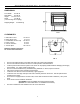
DECIDING WHERE TO LOCATE YOUR STOVE DIMENSIONS: Front Width: 22"/ 56 cm Rear Width: 22"/ 56 cm Height: 27-1/2"/ 70 cm* Depth 19"/ 48 cm (*not including vent coupling) Shipping Weight: 210 lbs/95 kg FIG. 1 CLEARANCES: A. Side wall to stove B. Rear wall to stove C. Combustible to stove Top D. Floor to stove E. Corner clearance F. Alcove depth 10"/ 25 cm 4"/ 10 cm 22”/ 56 cm 0"/ 0 cm 2"/ 5 cm 48"/ 122 cm Maintain sufficient clearances for service and maintenance FIG.
VENT TERMINAL CLEARANCES H= *Not to be installed above a meter/regulator assembly within 3 feet (90 cm) horizontally from the center-line of the regulator I= Clearance to service regulator vent outlet [*6 feet (1.8m) minimum] J= Clearance to non-mechanical air supply inlet to building or the combustion air inlet to any other appliance [12 inches (30 cm) minimum] K= Clearance to a mechanical air supply inlet [*6 feet (1.
These models have been tested and certified for use with SIMPSON DURAVENT DIRECT VENT TYPE "GS" PIPE FOR GAS STOVES. SECURITY VENTING SYSTEMS (SECURE VENT) Kits are available for vertical venting or horizontal venting. It is recommended that a bead of RTV High Temperature Silicone be applied to each outer vent joint and milpac to each inner joint before installation. This model has also been tested for horizontal venting installations when using SHERWOOD INDUSTRIES LTD.
When planning your installation, it will be necessary to select the proper length of vent pipe for your particular requirements. It is important to note when passing through a wall, the maximum allowable wall thickness is 10-inches (254mm), 1 ½ inches clearance to combustibles must be maintained. Select the amount of vertical rise desired for “vertical-to-horizontal” type installations.
STEP 7. Slide the decorative wall thimble up to the wall surface and attach with the screws provided. Apply decorative brass or chrome trim if desired. FIG-14. FIG. 11 FIG. 12 FIG-13 FIG-14 NOTES: (1) The four wood screws provided should be replaced with the appropriate fasteners for stucco, brick, concrete, or other types of siding. (2) For buildings with vinyl siding, a vinyl siding standoff (950), should be installed between the vent cap and the exterior wall FIG-12.
VERTICAL INSTALLATION STEP 1. Check the instructions for required clearances (air spaces) to combustibles when passing through ceilings, walls, roofs, enclosures, attic rafters , or other nearby combustible surfaces. Do not pack air spaces with insulation. STEP 2. Set the gas appliance in the desired location. Drop a plumb bob down from the ceiling to the position of the appliance flue exit, and mark the location where the vent will penetrate the ceiling. Drill a small hole at this point.
NOTES: (1) If an offset is necessary in the attic to avoid obstructions, it is important to support the vent pipe every 3 feet, to avoid excessive stress on the elbows, and possible separation. Wall straps are available for this purpose. FIG-18 (2) When ever possible, use 45° degree elbows instead of 90° degree elbows. The 45° degree elbow offers less restriction to the flow of flue gases and intake air. NOTES: (1) For multi story installations.
CATHEDRAL CEILING INSTALLATION STEP 1. Follow installation steps 1 and 2 under Vertical Termination. STEP 2. Using the plumb bob, mark the centerline of the venting system on the ceiling and drill a small hole through the ceiling and roof at this point. From the roof, locate the drill hole and mark the outline of the “Cathedral Ceiling Support Box”. STEP 3. Remove shingles or other roof coverings as necessary to cut the rectangular hole for the “Support Box”.
Install 2 spring spacers around the flex pipe. Slide the horizontal section of pipe over the flexible liner and install through the wall thimble, ensure that this portion of pipe slides onto the vent termination cap. Slide the inside finished collar over the horizontal section of pipe and secure to wall using the screws provided. Slide the 90° elbow over the flex pipe. Stretch the flex liner to a length long enough to ensure the flex liner can be easily connected to the flue outlet of the appliance.
VENTING INTO CLASS “A” CHIMNEYS Simpson GS Dura vent cap This model is also certified and tested to vent into CLASS “A” wood. stove chimneys Place the freestanding direct vent appliance in the desired location. Cap Adapter Using Simpson Dura Vent conversion kit #s 931-932933, depend on the ID diameter of the CLASS “A” chimney that this appliance is to be vented into. Class “a Chimney Place a bead of high temperature silicone or mil pac at each connection to ensure a tight seal.
INSTALLATION OF LOGSET and EMBERS INSTALLING THE GLOWING EMBERS A bag of Rock Wool embers is provided for use on the burner. CAUTION: Use only the type of ember material supplied with this appliance. Due to the amount of ember material there may be more than required. If over time, through cleaning and servicing, these embers require replacement, contact your nearest ENVIROGAS dealer for replacement embers. Remove the ember material from the plastic bag. Cover the shaded areas in the diagram shown beside.
OPERATING INSTRUCTIONS FOR YOUR SAFETY READ BEFORE OPERATING WARNING: IF YOU DO NOT FOLLOW THESE INSTRUCTIONS EXACTLY, A FIRE OR EXPLOSION MAY RESULT CAUSING PROPERTY DAMAGE, PERSONAL INJURY OR LOSS OF LIFE. A) This appliance is equipped with a pilot, which must be lit by • If you cannot reach your gas supplier, call the fire hand by following these instructions exactly. department.
MAINTENANCE AND TECHNICAL To Replace: • open door fully • Lift door vertically so that hinge pins lift out of hinge receivers. • Return the door assembly to dealer. Door and glass assembly must be replaced as a complete unit by your ENVIROGAS Dealer. No substitute materials are allowed. Periodically check to ensure that your "Direct Vent" system is clear. Periodically check the pilot and burner. Check to see that all the burner ports are clean and clear. Check the pilot head for blockage.
TROUBLE SHOOTING Problem Spark will not light the pilot after repeated pressing of spark igniter Pilot will not remain lit Burners will not remain lit Flame lifting Glass fogs up Blue flames Flames are burning “dirty” or Sooting Possible Cause Defective piezo igniter Solution Check connections to igniter -If igniter connections are good but there is no spark-replace igniter Broken spark electrode -Check for broken ceramic insulation replace, electrode if broken Miss-aligned spark electrode -If spark i
GAS LINE CONNECTION ORIFICE SIZES, PRESSURE AND BTU’S NATURAL GAS #42 dms 3.8” wc (0.95 kPa) 1.1” wc (0.27 kPa) 7.0” wc (1.74 kPa) 5” wc (1.25 kPa) 26,500 Btu/h(7.87 kW) 13,500 Btu/h(3.9 kW) 21,000 Btu/h(6.15 kW) 21,500 Btu/h(6.3 kW) Main Orifice Manifold pressure. Min. Manifold pressure. Supply Pressure. Min. Supply pressure. Max. BTUH Input. Min. BTUH Input. Output fan off Output fan on PROPANE GAS #53 dms 11” wc (2.74 kPa) 2.7” wc (0.67 kPa) 12” wc (2.98 kPa) 11.5” wc (2.86 kPa) 26,500 Btu/h(7.
The ENVIROGAS EG 28.FS.DV. will operate with no external power supply. These models have a Millivolt gas control which uses the pilot flame to generate enough electricity to operate the main burner. The appliance when installed, must be electrically connected and grounded in accordance with local codes or in the absence of local codes, with the current CSA C22.1 CANADIAN ELECTRICAL CODE. Part 1, SAFETY STANDARDS FOR ELECTRICAL INSTALLATIONS, or THE NATIONAL ELECTRICAL CODE ANSI / NFPA 70 in the USA.
PARTS AND ACCESSORIES Service Parts available from your local Envirogas Dealer Burner Control Assembly Natural Gas Pilot Assembly Propane Pilot Assembly Door Bolt Relief Door Gasket Regulating Valve Piezo Igniter Burner Switch B-vent Spill switch 220° Orifice Blank Convection Blower Light Bulb Holder Light Switch (momentary) Fan Controller Log Set (with Embers) Thermocouple Embers Thermopile Door Gasket Convection Fan Sensor 120° (48°C) Accessories Gold trim Package Low Voltage Thermostat INSTALLING OR R
ADJUSTING THE VENTURI • • • • Remove the ash shelf by undoing the screw at each end, pull shelf towards you. Remove one screw from the cover plate located below the ash shelf. Loosen the other screw (do not remove) swing the cover plate out of the way and tighten screw down to hold it in place. With along screwdriver rotate spring clips to open or close the shutter to the desired setting. The burner flame should be a bright yellow/orange when hot.
WARRANTY Sherwood Industries Ltd. offers a *Lifetime Warranty on this gas product. The lifetime warranty covers the appliance for a period of seven years from the date of installation. This warranty applies only to the original owner in the original location Covered under the lifetime warranty are Cabinet Sides, Tops, Pedestals, Surround Panels and Chassis and Heat Exchanger.
PARTS LIST EC-001 EC-002 EC-006 EC-007 EC-009 EC-011 EC-012 EC-013 EC-014 EC-015 EC-016 EC-019 120° F CERAMIC TEMP SENSOR 220° F CERAMIC SPILL SWITCH SIT NOVA 820 NG VALVE 50% SIT NOVA 820 LP VALVE 50% THERMOCOUPLE (POST 10/00) SPARK ELECTRODE w/CABLE THERMOPILE PILOT NG w/ELECTRODE PILOT LP w/ELECTRODE FULLY ASSEMBLED PILOT NG FULLY ASSEMBLED PILOT LP PILOT ORIFICE NG EG28-108 EG28-109 EG28-116 EG28-120 EG28-121 EG28-123 EG28-124 EG28-125 EG28-126 EG28-129 EG28-130 EG28-131 FREESTANDING PEDESTAL FS PEDE
BV 4” CRIMPED FLUE PIPE 120 ° F (49° C) CERAMIC FAN TEMP SENSOR FS BV STOVE TOP EG28124 EG28-169 DV 4” FLARED FLUE PIPE EC-001 FS DV STOVE TOP EG28-126 EG28-170 CONVECTION BLOWER BV TOP BAFFLE EG28-132 DV TOP BAFFLE EC-030 EG28-131 FS FAN MOUNTING BRACKET FS CABINET SIDE PANEL EG28-304 EG28-123 WIRE CHANNEL EG28-139 DOOR MAGNET AND BRACKET 220° F (104° C) CERAMIC SPILL SWITCH EC-002 UPPER GOLD BARS 1 X 1 SIDE CABINET HINGE EG28-129 LOWER GOLD BAR EC-054 EG28-130 FS CABINET SIDE PA
FULLY ASSEMBLED PILOT PAN BURNER TOP EC-015 NG , 016 LP BURNER CONTROL ASSEMBLY COMPLETE PAINTED DOOR ASSEMBLY WITH GLASS (A+B) THERMOPILE EC-012 EG28-143 NG EG28-145 LPG EG28-099 THERMOCOUPLE VENTURI TUBE EC-009 GOLD DOOR ASSEMBLY WITH GLASS (A+B) PILOT ORIFICE EG28-101 EC-019 NG, 020 LP SPARK ELECTRODE EC-011 BURNER BRACKET GLASS RETAINER ORIFIC E BLANK GAS TRAY TOP AND SIDES EC 022 GLASS EXTRUSIONS DOOR LATCH BOLT EC-059 DOOR LATCH STRIP FS LIGHT BULB HOLDER EC-031 S.I.
INSTALLATION DATA SHEET The installer for warranty purposes and future reference must record the following information. Please keep this information for your records.