PELLET STOVE EF- i OWNER’S TECHNICAL MANUAL SHERWOOD INDUSTRIES LTD.
ENVIROFIRE INSTALLATION MANUAL TABLE OF CONTENTS INTRODUCTION Important Safety Data......................................................................3 Pellet Quality ...................................................................................4 Warnings and Recommendations....................................................5 Automatic Safety Features ..............................................................5 OPERATION How to Start Your Pellet Stove ...........................................
IMPORTANT SAFETY DATA Please read this entire manual before installation and use of this pellet fuel burning room heater. Failure to follow these instructions could result in property damage, bodily injury or even death. CAUTION: DO NOT CONNECT OT ANY AIR DISTRIBUTION DUCT OR SYSTEM; DO NOT BURN GARBAGE OR FLAMABLE FLUIDS SUCH AS GASOLINE, NAPTHA OR ENGINE OIL; HOT WHILE IN OPERATION. KEEP CHILDREN, CLOTHING AND FURNITURE AWAY. CONTACT MAY CAUSE SKIN BURNS.
PELLET QUALITY IS IMPORTANT, PLEASE READ THE FOLLOWING PAGE Your pellet stove has been designed to burn wood pellets only. Since there are many manufacturers of wood pellets it is important to select pellets that are free of dirt or any impurities. The Pellet Fuel Industries (P.F.I.) has established standards for wood pellet manufactures. We recommend the use of pellets that meet or exceed these standards. Ask your dealer for a recommended pellet type.
WARNINGS AND RECOMMENDATIONS A. Do not abuse the glass by striking or slamming the door shut. B. Do not attempt to operate the stove with broken glass. C. Do not attempt to open the door and clean the glass while the unit is in operation. If you must clean the glass, use a soft cotton cloth and mild window cleaner. D. Do not use abrasive cleaners to clean the surface or any part of the stove. E. It is recommended that the unit be secured into its position in order to avoid any displacement. F.
HOW TO START YOUR PELLET APPLIANCE 1. Fill hopper with pellets. 2. Switch the power on by pushing the rocker switch to the manual position. FAN CONTROLLER 3. Turn Dial A Fire knob to the 12 o’clock position. (The lower grade pellets may need a higher setting on the feed rate.) 4. Approximately 15 minutes after the fire was lit, the green light should come on. WHEN THE GREEN LIGHT COMES ON, PUSH THE ROCKER SWITCH TO THE AUTO POSITION. Now the stove will shut off automatically if the fire goes out.
SLIDER/DAMPER INSTALLATION /OPERATIONS INSTRUCTIONS This is used to regulate the airflow through the pellet stove. INSTALLATION: 1. Remove the slider rod (short rod with knob and nuts) and the two nuts from their package and open the left side panel. This is the smaller of the two rods. Remove the knob from the knob. 2. Remove the knob and the outer nut from the rod. Push the rod through the hole in the slider.
AREAS FOR ROUTINE INSPECTION The following should be inspected periodically to ensure that the appliance is operating at its optimum and giving you excellent heat value: 2-3 DAYS/WEEKLY Burn Pot and Liner Ash Pan Inside Firebox Behind Firebox Liners Door Glass Heat exchanger tubes Ash pan and Door gaskets SEASONALLY or 2 TONS OF FUEL Exhaust Vent and Fresh Air Intake Tube Blower Mechanisms Heat exchanger tubes Latch Mechanism of ash pan Door Latch All Hinges Post Season Clean-up TOOLS REQUIRED TO CLEAN UN
DOOR GLASS (It is recommended that your dealer replace the glass if broken.) The door glass is made of 5 mm thick, high temperature PYROCERAMIC The center panel is 229 mm x 330 mm. To replace the glass, unscrew and remove the four glass retainers. Remove the glass and any broken pieces. High temperature fiberglass tape should be used around the glass. Replace the glass, center the glass assembly in the frame, then screw the glass retainers back to the frame. The use of substitute materials is prohibited.
ELECTRICAL COMPONENT FUNCTIONS The following is a list of electrical components and their functions on the ENVIROFIRE EF-IIi pellet stove. 1. CONVECTION FAN CONTROLLER This controller is responsible for varying the speed of the convection blower. The stove has a fan control-override. Should the convection blower be set on low and the Dial-A-Fire set on high, the convection blower will bypass the fan controller and go to high. This will cool the stove until control is given back to the fan controller.
10. 160F (71C) TEMPERATURE SENSOR When this sensor (located on the left side firewall) reaches 160F (71C), the convection blower will go to high, cooling the unit. 11.
DECIDING WHERE TO LOCATE YOUR PELLET APPLIANCE 1. Check clearances to combustibles. 2. Do not obtain combustion air from an attic, garage or any unventilated space. Combustion air may be obtained from a ventilated crawlspace. 3. Do not install the stove in a bedroom. 4. You can vent the stove through an exterior wall behind the unit or connect it to an existing masonry or metal chimney (must be lined if the chimney is over 6” in diameter, or less than 28 sq. inches cross sectional area).
REMOVING YOUR NEW STOVE FROM IT’S PALLET To remove your new stove from its pallet, open the left and right side panels. There are two wood screws that are holding the bottom of the stove to the pallet. Remove the screws. Close the side panels. See PAGE 18 how to install the pedestal. INSERT MODEL FREESTAND MODEL REMOVE SCREW HERE DIMENSIONS 22” SURROUND PANEL 11 ½” 24” 30.
MASONRY FIREPLACE INSERT INSTALLATION, MODEL FPI The Fireplace insert model includes a surround faceplate and a pedestal. When installing this unit, ensure that the pedestal is removed from the inside of the hopper and installed on the bottom of the unit.
ASSEMBLING THE FACE PLATE FOR THE FPI AND BIH MODELS 1. Assemble the brass frame using the corner hardware and screws supplied in the face place packaging. Install corner hardware into the side brass, then push into the top frame. Do not overtighten or the side bass cannot be removed during servicing. 2. Assemble the three faceplates to the stove by screwing in the hinged panels to the stove side panels. Loosen the front hopper lid screws and center the top panel under the hopper lid, tighten screws.
RECOMMENDED FRAMING FOR BUILT IN HEATER When installing model BIH it is recommended that you use the dimensions shown in the diagram below. These clearances will make it easy and readily accessible for service. BUILT IN HEATER CLEARANCES TO COMBUSTIBLES This unit includes a 3” (75 mm) pedestal and surrounding faceplates. The part of the unit behind the faceplate can be enclosed with combustible material. Model BIH has 1” (25 mm) standoffs to establish clearances to combustibles to the back, top and sides.
CLEARANCES TO COMBUSTIBLES CLEARANCE TO COMBUSTIBLES (FREESTANDING) - Side wall to unit A- 6 INCHES (150 mm) - Back wall to unit B- 1 INCH (25 mm) - Corner to unit C- 1 INCH (25 mm) - Mantle (Hearth Mount) 8 INCHES ( - Combustible flooring underneath the unit and extending 6 INCHES (150 mm) to the sides and front must be protected by a non combustible material. ALCOVE DIMENSIONS Minimum Alcove width........... Minimum Alcove height ......... Maximum Alcove depth ........
MODEL FS (FREESTANDING) INSTALLATION PEDESTAL INSTALLATION Model FS comes with a pedestal that has to be attached prior to installation: - Remove the pedestal from the box Remove the ENVIROFIRE unit from the box Place the unit on its back, making sure not to damage the wiring. Back off the screws on the base, install the pedestal over the screws. Lock pedestal in place using the keyholes, tighten the screws. Return unit to upright.
HORIZONTAL EXHAUST THROUGH THE WALL 1. NOTE: Use only listed type “PL” or “L” pellet venting products. Failure to use listed components may cause damage or personal injury or death. 2. Choose a location for your stove that meets the requirements stated in this manual and allows installation with the least amount of interference to house framing, plumbing, wiring, etc. 3. Install a non-combustible hearth pad underneath the unit extending 6 inches (15 cm) in front of and to the sides (where necessary).
THROUGH WALL INSTALLATION 1” 20
INSIDE VERTICAL INSTALLATION, MODEL FS 1. Choose a stove location that is ideal. See the section Deciding Where to Locate Your Pellet Appliance. 2. Place on a noncombustible hearth pad where necessary. 3. Place the unit on a hearth pad and space it in a manner so when the pellet vent is installed vertically, it will be 3” (5 mm) away from a combustible wall. 4. Locate the center of the fresh air intake pipe on the unit.
OUTSIDE VERTICAL PIPE INSTALLATION To accomplish the above titled installation, follow steps 1 through 8 in the previous section (HORIZONTAL EXHAUST THROUGH THE WALL) and then finish it by performing the following: 9 Install a tee with clean out on the outside of the house. 10 Install PL vent upward from the tee. Make sure that you install support brackets to keep the vent straight and secure. 11 Secure the flashing as you go through the roof.
MOBILE HOME INSTALLATION - Secure the heater to the floor using the two bolt holes in the pedestal. - CAUTION: THE STUCTURAL INTEGRITY OF THE MANUFACTURED HOME FLOOR, WALL, AND CEILING/ROOF MUST BE MAINTAINED. - Ensure the unit is electrically grounded to the chassis of your home (permanently). - Do not install in a room people sleep in. - Outside fresh air is mandatory in homes of tight construction and Mobile Homes OUTSIDE FRESH AIR CONNECTIONS A Fresh air intake is strongly recommended.
TROUBLESHOOTING DO NOT: - Switch the stove ON and OFF rapidly. This may cause current spikes, which could shorten the life of the electrical components. Service the stove with wet hands. The stove is an electrical appliance, which may pose a shock hazard if handled improperly. Only qualified technicians should deal with possible internal electrical failures. Remove any screws in the firebox without first lubricating them with penetrating oil.
3) The stove will not function in the “AUTO” mode when hot - If the unit fails to operate, by-pass the auto side of the switch by inserting a jumper wire between the dual black wires and the dual brown wires located on the back of the switch. Plug the stove back in. if the stove operates , Replace the switch. 4) The exhaust blower will not function normally - Open the left side panel, check all connections against the wiring diagram.
8) POTENTIOMETER READINGS: Full clockwise (switched off) = open circuit, overload or infinite resistance LOW FIRE 800K OHMS to 900K OHMS HIGH FIRE 68K OHMS to 82K OHMS If the range does not vary or the switch does not close then replace the potentiometer. The stove will not shut down - Make sure the auto/manual switch is in the auto position. Check the connections to the 120F (49C)-N/O temperature sensor and the auto/manual switch against the wiring diagram.
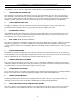
WIRING DIAGRAM 27
WARRANTY Sherwood Industries Ltd. gives a five year limited warranty on all steel manufactured parts. A one-year warranty is provided on all electrical components. The above limited warranties are extended only to the original purchaser. There is no warranty on the following parts: - fiberglass rope baskets refractory material burn pot liner paint enamel finish or gold plating where it applies, and, vacuum hose.