ENGLISH SAFETY INSTRUCTIONS 1. Read Instructions - All the safety and operating instructions should be read before the product is operated. 2. Retain instructions - The safety and operating instructions should be retained for future reference. 3. Heed Warnings - All warnings on the product and in the operating instructions should be adhered to. 4. Follow Instructions - All operating and use instructions should be followed. 5. Cleaning - Unplug this product from the wall outlet before cleaning.
Introduction CAUTION This symbol is intended to alert the user to the presence of uninsulated "dangerous voltage" within the product's enclosure that may be of sufficient magnitude to constitute a risk of electric shock to persons. : TO REDUCE THE RISK OF ELECTRIC SHOCK, DO NOT REMOVE COVER (OR BACK). NO USER-SERVICEABLE PARTS INSIDE. REFER SERVICING TO QUALIFIED SERVICE PERSONNEL.
ENGLISH CONTENTS • SAFETY INSTRUCTIONS . . . . . . . . . . . . . . . . . . . . . . . . . . . . . . . . . . . . . . . . . . . . . . . . . . . . . . . 2 • Introduction READ THIS BEFORE OPERATING YOUR UNIT . . . . . . . . . . . . . . . . . . . . . . . . . . . . . . . 3 • System Connections . . . . . . . . . . . . . . . . . . . . . . . . . . . . . . . . . . . . . . . . . . . . . . . . . . . . . . . . . . 5 • Front Panel Controls . . . . . . . . . . . . . . . . . . . . . . . . . . . . . . . . . . . . . . . . .
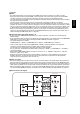
• Please be certain that this unit is unplugged from the AC outlet before making any connections. • Since different components often have different terminal names, carefully read the operating instructions of the component connected. • Be sure to observe the color coding when connecting audio, video and speaker cords. • Make connections firmly and correctly. If not, it can cause loss of sound, noise or damage to the receiver. 1 13 5 4 12 11 6 3 9 8 9 10 7 2 9 15 14 1.
ENGLISH 2. CONNECTING VIDEO COMPONENTS • The jacks of VIDEO 1 may also be connected to a DVD recorder or other digital video recording component. For details, refer to the operating instructions of the component to be connected. • The jacks of VIDEO 2/VIDEO 3 can also be connected to an additional video component such as a cable TV tuner or satellite system. • Connect the jacks of VIDEO 3 to the video component in the same way.
Notes : • For stable signal transfer, we recommend using HDMI cords that are a maximum of 5 meters in length. • Among the components that support HDMI, some components can control other components via the HDMI connector. However, this unit cannot be controlled by another component via the HDMI connector. • The audio signals from the HDMI connector (including the sampling frequency and bit length) may be limited by the component that is connected.
ENGLISH Continued Notes : • When the VIDEO MODE is set to "AUTO" or "HDMI", if the 480i ~ 1080i video signals are input into the HDMI IN connector, the HDMI video signals are output from the HDMI MONITOR OUT only. • When the VIDEO MODE is set to "AUTO" or "COMPONENT" and no video signals are input into the HDMI IN, if 480i video signals are input into the COMPONENT INs, the component video signals are output from the MONITOR OUTs.
3. CONNECTING AUDIO COMPONENTS ENGLISH • The TAPE IN/OUT jacks can be connected to audio recording equipment such as a tape deck, an MD recorder, etc. 4. CONNECTING EXTERNAL INS • Use these jacks to connect the corresponding outputs of a DVD player or external decoder, etc. that has 6, 7 or 8 channel analog audio outputs. • In case of 6 or 7 channel outputs, do not connect both of the SURROUND BACK L and R inputs or the SURROUND BACK R input of this unit.
ENGLISH 5. CONNECTING DIGITAL INS AND OUT • The OPTICAL and the COAXIAL DIGITAL OUTs of the components that are connected to this unit can be connected to these DIGITAL INs. • A digital input should be connected to the components such as a CD player, DVD player, etc. capable of outputting DTS Digital Surround, Dolby Digital or PCM format digital signals, etc. • If the component with OPTICAL IN jack is connected to the OPTICAL OUT jack of this unit, you can record the high quality sound of CDs, etc.
7. CONNECTING SPEAKERS ENGLISH • Be sure to connect speakers firmly and correctly according to the channel(left and right) and the polarity (+ and -). If the connections are faulty, no sound will be heard from the speakers, and if the polarity of the speaker connection is incorrect, the sound will be unnatural and lack bass. • For installing the speakers, refer to "Speaker placement" on page 12.
ENGLISH Speaker placement Ideal speaker placement varies depending on the size of your room and the wall coverings, etc. The typical example of speaker placement and recommendations are as follows : ■Front left and right speakers and center speaker • Place the front speakers with their front surfaces as flush with TV or monitor screen as possible. • Place the center speaker between the front left and right speakers and no further from the listening position than the front speakers.
8. CONNECTING XM (only for North America) ENGLISH • Connect the XM terminal to the XM Mini-Tuner system (sold separately). • Position the XM Mini-Tuner system near a south-facing window to receive the best signal. When making connections, also refer to the operating instructions of the XM Mini-Tuner system.
ENGLISH 10. CONNECTING RF REMOTE ANTENNA • Connect the supplied antenna to receive the RF (Radio Frequency) beams from the universal remote control. • If the antenna is connected to this receiver, even though there are obstacles such as walls, furniture, etc. in the way, you can control this receiver with the universal remote control. Therefore, you can control this receiver from another room with the universal remote control without connecting the multi-room system kit.
• Connect a component to DC TRIGGER OUT jack that allows DC 12V to turn on when a specific input source is selected. • For details, refer to the operating instructions of the components to be connected. • To link DC TRIGGER OUT with a specific input source, refer to "When selecting the DC TRIGGER" on page 59. Notes : • This output voltage (12V d.c., 100mA) is for (status) control only, it is not sufficient for drive capability.
ENGLISH Front Panel Controls 1. POWER switch 2. POWER ON/STANDBY button/indicator 3. VIDEO INPUT SELECTOR button 4. AUDIO INPUT SELECTOR button 5. EXTERNAL IN button 6. TUNER button 7. AUDIO ASSIGN button 8. MASTER VOLUME CONTROL knob 9. HEADPHONE jack 10. SPEAKER button 11. PURE AUDIO button 12. SURROUND MODE button 13. STEREO button 14. SETUP button 15. CHANNEL LEVEL button 16. CONTROL UP(▲)/DOWN(▼) buttons 17. ROOM 2 button 18. MEMORY/ENTER button 19. TUNING UP(+)/DOWN(-) buttons 20.
SETUP MIC JACK ENGLISH • To use Auto Setup function, connect the supplied microphone to the SETUP MIC jack.(For details, refer to "When selecting the AUTO SETUP" on page 61.) Notes: • Because the microphone for Auto Setup is designed for use with this receiver, do not use a microphone other than the one supplied with this receiver. • After you have completed the auto setup procedure, disconnect the microphone.
ENGLISH Universal Remote Controls This universal remote control can operate not only this receiver but also most popular brands of audio and video components such as CD players, tape decks, TVs, cable boxes, VCRs, DVD players, satellite receivers, etc. • To operate 7 components other than this receiver , you should enter the setup code for each component. (For details, refer to “USING FUNCTIONS OF REMOTE CONTROL” on page 21.
ENGLISH FUNCTION TABLE of the NUMBERED BUTTONS. Notes : • Some functions for each component may not be available or may work differently. • Depending on other kinds of components that are available for each DEVICE button, some functions may not be available or may work differently, too. • For details about functions, refer to the operating instructions of each component.
OPERATING COMPONENTS WITH REMOTE CONTROL ENGLISH 1. Enter the setup code for each REMOTE CONTROL OPERATION RANGE In case that this remote control emits the infrared beams • Use the remote control within a range of about 7 meters (23 feet) and angles of up to 30 degrees aiming at the remote sensor. component other than this receiver. For details, refer to "Entering a setup code" on page 21. 2. Turn on the component you want to operate. 3.
• This remote control can control up to 8 different components. • Before operating audio and video components other than this receiver with using this remote control, the setup code for each component should be entered. • For system remote control operation, "000" was stored previously in the memory of the device button "CD" for Sherwood CD player, "DVD" for Sherwood DVD player, "AUX" for Sherwood tape deck and "TV" for Sherwood TV respectively as its factory setup code.
6. Operate the component using the corresponding 3. While "PRESET" is displayed, search a setup ENGLISH function buttons. code, aiming the remote control at the remote sensor on the component. • If any of buttons fails to operate as they should, start from the step 1 again to enter the correct setup code. Note : • Manufacturers may use different setup codes for the same product category.
4. While "SEL" is flickering, on this remote control, Programming the commands from other remote controls (LEARNING mode) • If the setup codes are not available for your component or you want to program a missing or special function into one button of a device, the learning function enables this remote control to learn the commands from other remote controls. Example: If the function to be learned is playback, press the PLAY(▶) button. 1.
ENGLISH Erasing the programmed command from one button Erasing all the commands programmed under a device mode 1. Perform the steps 3 and 4 in "Entering a setup 1. Perform the steps 3 and 4 in "Entering a setup code" procedure on page 21 to select the deleting mode ("DELETE"). code" procedure on page 21 to select the deleting mode ("DELETE"). • Then "BTTN" is displayed on the LCD screen for several seconds. • Then "BTTN" is displayed on the LCD screen for several seconds. 2.
Programming a macro function • The macro function enables you to program a series of button operations(up to 15) on this remote control into a single button. • You can store up to three separate macro command sequences into "M1", "M2" and "M3" buttons. 3. While "SEL" is flickering, press the operation Example: When playing a DVD on the DVD player connected to VIDEO 2 jacks of this receiver. ①. Press "AUDIO" button to control this receiver. ②. Press "POWER ON" button to turn this receiver on. ③.
ENGLISH Operating a macro function • Aim the remote control at the REMOTE SENSORs of the components to be controlled and press the MACRO button you want. Example : When pressing "M1" button. 2. While "VOL" is displayed, press the CURSOR UP(▲)/DOWN(▼) buttons to select the desired punch-through mode, then press the ENTER button. Notes: • The codes programmed into a MACRO button will be transmitted at an interval of 0.5 seconds. However, some components may not be able to complete one operation in 0.
Continued • While this remote control is set to control a master device, aim the remote control at the REMOTE SENSOR of the punch-through device and press the desired button of the programmed punch-through controls. Example: When pressing "PLAY (▶)" button. CURSOR UP(▲)/DOWN(▼) buttons to select the desired punch-through device, then press the ENTER button.
Continued ENGLISH 3. While the device is displayed, press the 2. While "VOL" is displayed, press the CURSOR CURSOR UP(▲)/DOWN(▼) buttons to select the one punch-through deleting mode ("DELETE"), then press the ENTER button. UP(▲)/DOWN(▼) buttons to select the all punch-through deleting mode ("DELETE").
3. While "RF" (or "IR") is displayed, press the Changing the transmission signal CURSOR UP(▲)/DOWN(▼) buttons to select the desired transmission signal, then press the ENTER button. ENGLISH • This remote control can emit not only the infrared beams which the conventional remote control uses but also the RF(Radio Frequency) beams which are stronger than those. • When you want to control this receiver from longer distance even if there are obstacles such as walls, furniture, etc.
ENGLISH ROOM 2 Remote Controls This remote control unit is an additional remote control unit for the ROOM 2 source playback only. • You can use the ROOM 2 functions with this remote control unit more conveniently in another room than with the universal remote control unit. • For details on ROOM 2 operation, refer to "ROOM 2 SOURCE PLAYBACK" on page 48. REMOTE CONTROL OPERATION RANGE • Aim the ROOM 2 remote control at the IR receiver installed in another room.
Notes: • Before operating this receiver with the supplied remote control, refer to "Universal Remote Controls" on page 18 for details about operation. • Before operating this receiver, first set this unit as desired for optimum performance, doing the OSD menu setting procedures. (For details, refer to "OSD Menu Settings" on page 50.) LISTENING TO A PROGRAM SOURCE 3. Select the desired input source. Before operation • Enter the standby mode. • The POWER ON/STANDBY button lights up amber.
6. Operate the selected component for playback. ENGLISH When CD, AUX, VIDEO 1~ 4 is selected as an input source • When playing back the program sources with surround sound, refer to "ENJOYING SURROUND SOUND" on page 36. • If the AUDIO MODE is set to the mode other than "DIGITAL" for the corresponding input source on the INPUT SETUP menu, you cannot hear the sound from the selected digital input. (For details, refer to "SETTING THE INPUT SETUP" on page 56.) 7. Adjust the (overall) volume. 4.
Listening with headphones ENGLISH Achieving higher purity of sound quality • The PURE AUDIO indicator lights up, the fluorescent display goes off and all the videorelated circuits are turned off, meaning no video signal transfer. • When the pure audio is activated, the optimum surround mode (or stereo mode, etc.) will be automatically selected depending on the signal format being input. • Press this button again to cancel the pure audio function. • Ensure that the SPEAKER button is set to off.
SURROUND SOUND ENGLISH • This receiver incorporates a sophisticated Digital Signal Processor that allows you to create optimum sound quality and sound atmosphere in your personal Home Theater. Surround modes ■DTS Digital Surround ■Dolby Digital DTS Digital Surround(also called simply DTS) supports up to 5.1 discrete channels and uses less compression for high fidelity reproduction. Use it with DVDs and CDs bearing the DTS logo.
under the US and foreign patents pending and other related technology owned by Neural Audio Corporation. ■Dolby Virtual Speaker This mode creates a virtual surround sound field using as few as two front speakers, allowing you to experience listening from 5.1 channel speakers. This mode is effective not only for 5.1 channel sources but also for 2 channel sources.
ENGLISH ENJOYING SURROUND SOUND Notes: • Before surround playback, first perform the speaker setup procedure, etc. on the OSD menu for optimum performance. (For details, refer to "SETTING THE SPEAKER/ROOM EQ SETUP" on page 61.) • When playing digital signals from the Dolby Digital program source or selecting the surround mode such as Dolby Pro Logic II /Dolby Pro Logic IIx Music, Dolby Headphone, Dolby Virtual Speaker modes, you can adjust their parameters for optimum surround effect.
Continued • Depending on the signal format which is being input, either the stereo mode or the 2CH downmix mode is selected. • To cancel either the stereo mode or the 2CH downmix mode, select the surround mode with using the MULTI CONTROL knob on the front panel or the SURROUND MODE UP/DOWN ( >/< ) buttons on the remote control. 2CH downmix mode • This mode allows the multi-channel signals encoded in DTS or Dolby Digital format, etc.
ENGLISH Adjusting the current channel level • After adjusting each channel level with test tone, adjust the channel levels either according to the program sources or to suit your tastes. • You can adjust the current channel levels as desired. These adjusted levels are just memorized into user’s memory ("CALIBRATE"), not into preset memory("REFERENCE 1", "REFERENCE 2"). 1. Press the CHANNEL LEVEL button. 3. Adjust the level of the selected channel as desired.
Recalling the memorized channel levels Memorizing the adjusted channel levels • You can memorize the adjusted channel levels into preset memory("REFERENCE 1", "REFERENCE 2") and recall the memorized whenever you want. ENGLISH 1. Press the CHANNEL LEVEL button. 1. After performing the steps 1~4 in "Adjusting the current channel level" procedure on page 38, press the (MEMORY/)ENTER button. • "REFERENCE 1" (or "CALIBRATE") is displayed for several seconds.
LISTENING TO RADIO BROADCASTS Manual tuning ENGLISH Auto tuning • Manual tuning is useful when you already know the frequency of the desired station. • After selecting the desired band, press the TUNING UP(+)/DOWN(-) buttons repeatedly until the right frequency has been reached. 1. Select the desired band. Auto presetting • Auto presetting function automatically searches for FM stations only and store them in the memory.
Manual presetting Tuning to preset stations • After selecting the tuner as an input source, select the desired preset number. ENGLISH • You can store up to 30 preferred stations in the memory. 1. Tune in the desired station with auto or manual tuning. 2. Press the MEMORY/ENTER button. Scanning preset stations in sequence • "MEMORY" is flickering for several seconds. 3. Select the desired preset number (1~30) and press the MEMORY/ENTER button.
XM Satellite Radio (only for North America) ENGLISH • This receiver is the XM Ready® receiver. You can receive XM Satellite Radio® by connecting to the XM Mini-Tuner system (sold separately) and subscribing the XM service. About XM Satellite Radio for U.S. & Canadian products XM Satellite Radio offers an extraordinary variety of commercial-free music, plus the best in sports, news, talk and entertainment. XM is broadcast in superior digital audio from coast to coast.
Channel search ENGLISH • In the XM mode, press the TUNING UP (+)/DOWN (-) buttons repeatedly to select the desired channel. Direct search • Direct search is useful when you already know the channel number. 2. While displaying "DIRECT SEARCH", select the desired channel number with pressing the NUMERIC (0 ~ 9) buttons. 1. In the XM mode, select the direct search mode. Examples: For "3" : For "27" : For "124" : • When "DIRECT SEARCH" disappears, repeat again from the above step 1.
Continued ENGLISH 3. Select displaying the selected category, select the desired channel. Presetting channels Preset search • You can store up to 30 preferred channels in the memory. • In the XM mode, select the desired preset channel. 1. Select the desired channel with preforming channel search, direct search or category search. 2. To memorize the channels, perform the steps 2 to 4 in "Manual presetting" procedure on page 41.
• The analog signals from the EXTERNAL INs as well as the digital signals from the HDMI IN, the OPTICAL or COAXIAL DIGITAL IN can be heard but cannot be recorded. • When recording the analog signals from CD, AUX, VIDEO 1~4, be sure to select "ANALOG" for the AUDIO MODE. (For details, refer to "When selecting the AUDIO MODE" on page 58.) • When recording the video signals from VIDEO 2~4, be sure to select "COMPOSITE" or "S-VIDEO" for the VIDEO MODE.
ENGLISH DIGITAL AUDIO RECORDING WITH MD RECORDER 2. For digital recording, select the digital input as • Only when the OPTICAL DIGITAL OUT of this receiver is connected to the OPTICAL DIGITAL IN of the MD recorder or CD recorder, you can enjoy high-quality sound of digital recording without converting the original signals.
OTHER FUNCTIONS Operating the sleep timer • The sleep timer allows the system to continue to operate for a specified period of time before automatically shutting off. • To set the receiver to automatically turn off after the specified period of time. • You can check the audio information on the input source on your monitor TV. Note : • When the component video signals or the HDMI video signals are input and these signals are output from the MONITOR OUTs, the audio information cannot be displayed.
ENGLISH ROOM 2 SOURCE PLAYBACK • This function allows enjoying one source in the main room and playing another in a different room at the same time. • When you connect the multi-room system kit to the IR IN jack of this receiver, you can control this receiver with not only the universal remote control unit but also the ROOM 2 remote control unit in a different room, too. (For details, refer to "CONNECTING MULTI-ROOM SYSTEM KIT" on page 14 and "ROOM 2 Remote Controls" on page 30.
Continued 1. Press the ROOM 2 button to enter the ROOM 2 3. Set the selected mode as desired. mode. • ROOM 2 ~ is displayed for several seconds. • When the ROOM 2 setting mode disappears, press the ROOM 2 button again. ■When selecting the ROOM 2 mode. ON : To turn on the ROOM 2 function. (" " lights up.) OFF : To turn it off. (" " or " " goes off depending on the AMP ASSIGN setting.) 2. Select the desired mode while displaying the ROOM 2 setting mode. ■When selecting the ROOM 2 input.
ENGLISH OSD Menu Settings • The OSD (On-Screen Display) menu is a setting menu that is displayed on the monitor TV and allows you to perform the setup procedures easily. In most situations, you will only need to set this once during the installation and layout of your home theater, and it rarely needs to be changed later. The OSD menu consists of 6 main menus ; system setup, input setup, speaker / room EQ setup, CH level setup, sound parameter and multi room setup.
ENGLISH 3. Confirm your selection. When selecting the SYSTEM SETUP When selecting the INPUT SETUP 52 56 When selecting the SPEAKER /ROOM EQ SETUP When selecting the CH LEVEL SETUP 61 67 When selecting the SOUND PARAMETER When selecting the MULTI ROOM SETUP 69 73 • For the setting details, see page in ⇨. • Adjust the setting(s) in each setting category to your preference. • When the SETUP button is pressed on a sub-menu, the menu screen will be turned off.
SETTING THE SYSTEM SETUP ENGLISH • AMP ASSIGN : To assign the surround back channels' power amplifier correctly depending on how to use the speakers. • SUBWOOFER MODE : To select the desired subwoofer mode. • HDMI AUDIO OUT : To output the digital audio signals from the HDMI MONITOR OUT connector. • TONE CONTROL : To adjust the tone (bass and treble) as desired. • CINEMA EQ : To select the desired cinema EQ mode.
Continued • "SW PLUS+" mode is valid only when "FRONT" and "CENTER" are set to "FULL RANGE" and "SUBWOOFER" is set to "YES" on the SPEAKER/ROOM EQ SETUP menu. (For details, refer to "SETTING THE SPEAKER/ ROOM EQ SETUP" on page 61.) NORMAL : When the low frequency signals of channels set to "FULL RANGE " are reproduced from those channels only.
Continued ENGLISH ②. Press the CURSOR UP(▲)/DOWN(▼) buttons to select the desired tone mode. ③. Press the CURSOR LEFT(◀)/RIGHT(▶) buttons to adjust the selected tone as desired. • The tone level can be adjusted within the range of -10 ~ +10 dB. • In general, we recommend the bass and treble to be adjusted to 0 dB (flat level). • Extreme settings at high volume may damage your speakers. • To complete tone adjustment, repeat the above steps ② and ③.
When selecting the OSD POSITION ADJUST 1. Press the CURSOR UP(▲)/DOWN(▼) buttons to select the OSD POSITION ADJUST, then press the ENTER button. 2. Press the CURSOR UP(▲)/DOWN(▼)/LEFT(◀)/RIGHT(▶) buttons to adjust the position of the momentary OSD and the OSD menu as desired. 55 ENGLISH • You can adjust the position of the momentary OSD and the OSD menu that are displayed on the monitor TV.
SETTING THE INPUT SETUP ENGLISH • This menu allows you to make the various settings depending on how to use the input sources connected to this receiver. When selecting the items other than NAME 1. Press the CURSOR UP(▲)/DOWN(▼) buttons to select the desired input source, then press the ENTER button. Example: When selecting the VIDEO 1 When selecting the menu of page 2 or page 1. • Press the CURSOR UP(▲)/DOWN(▼) buttons to select "GO TO NEXT ~ ", then press the ENTER button. 2.
Continued • You should assign the connected HDMI INs to the desired of VIDEO 1 ~ VIDEO 4. (For details, refer to "CONNECTING VIDEO COMPONENTS" on pages 6 ~ 8.) • You can select the desired of HDMI 1 ~ HDMI 4.
Continued ENGLISH When selecting the AUDIO MODE • You can select the desired audio input signal to be played. ■Notes : • Be sure to set the AUDIO MODE to the audio input which is connected and assigned to the selected input source. • When the HDMI AUDIO OUT is set to ON, no sound will be heard from the speakers connected to this receiver (except ROOM 2 speakers).
Continued • Depending on how to select a surround mode, you can select the auto surround mode or the manual surround mode. ON : The optimum surround mode will be automatically selected depending on the signal (Auto surround mode) format being input. OFF (Manual surround mode) : You can select the desired of different surround modes selectable for the signal being input with using the MULTI CONTROL knob or the SURROUND MODE UP/DOWN ( >/< ) buttons.
When selecting the NAME ENGLISH • You can give names to the input sources other than tuner. • Up to 7 characters can be entered for each name. 3. Press the CURSOR LEFT(◀)/ RIGHT(▶) buttons to select the desired digit. 1. Press the CURSOR UP(▲)/DOWN(▼) buttons to select the desired input source, then press the ENTER button. • Then the selected digit will flicker. 4. Press the CURSOR UP(▲)/DOWN(▼) buttons to enter the desired character on the flickering digit.
• After you have installed this receiver and connected all the components, you should adjust the speaker settings for the optimum sound acoustics according to your environment and speaker layout. • Even when you change speakers, speaker positions, or the layout of your listening environment, you should adjust the speaker settings, too. • When performing the AUTO SETUP procedure, you need not perform the SPEAKER CONFIGURATION, SPEAKER DISTANCE, SPEAKER CROSSOVER and CH LEVEL SETUP procedures.
Continued ENGLISH 2. Press the CURSOR UP(▲)/DOWN(▼) buttons to select the AUTO SETUP, then press the ENTER button. 3. Press the CURSOR UP(▲)/DOWN(▼) buttons to select the START, then press the ENTER button. When the auto setup has been completed. • Loud test tones are output successively and then if a series of auto setup procedure has been completed, "COMPLETED" will be displayed. • To stop the auto setup procedure while performing it, press the ENTER button.
Continued When selecting the SPEAKER CONFIGURATION 1. Press the CURSOR UP(▲)/DOWN(▼) buttons to select the SPEAKER CONFIGURATION, then press the ENGLISH ENTER button. 2. Press the CURSOR UP(▲)/DOWN(▼) buttons to select the desired speaker. 3. Press the CURSOR LEFT(◀)/ RIGHT(▶) buttons to set the selected speaker as desired. YES/NO: Select the desired depending on whether the speakers are connected or not.
When selecting the SPEAKER DISTANCE 1. Press the CURSOR UP(▲)/DOWN(▼) buttons to select the SPEAKER DISTANCE, then press the ENTER ENGLISH button. 2. Press the CURSOR UP(▲)/DOWN(▼) buttons to select the desired item. Note : • You cannot select the subwoofer and the speakers set to "NO". 3. Press the CURSOR LEFT(◀)/RIGHT(▶) buttons to set the selected item as desired. When selecting the desired unit • You can select either METERS or FEET.
• Set the crossover frequency according to the frequency characteristics of the speakers connected. (For details on the frequency characteristics, refer to the operating instructions of the speakers.) • If the frequency range of your speaker is 100 Hz ~ 20 kHz, the crossover frequency should be set to 100 Hz (or slightly higher). • The low frequencies below the crossover frequency are to output from subwoofer or the speakers which are set to "FULL RANGE" (when not using a subwoofer). 1.
ENGLISH When selecting the ROOM EQ SETUP • The room EQ is a kind of room equalizer for your speakers. According to the acoustic characteristics of your room measured by the auto setup, the room EQ automatically adjusts the frequency response of your speakers. • If you use different brands or sizes of speakers for some channels or have a room with unique acoustic characteristics, such as walls, furniture, and the dimensions or the shape of the room, we recommend using the room EQ.
SETTING THE CH LEVEL SETUP ■Note : • Depending on the speaker settings("NO", etc.), some channels cannot be selected. Adjusting the current channel level • You can adjust the current channel levels as desired. These adjusted levels are just memorized into user’s memory("CALIBRATE"), not into preset memory("REFERENCE 1", "REFERENCE 2"). • After adjusting each channel level with test tone, adjust the channel levels either according to the program sources or to suit your tastes.
Memorizing the adjusted channel levels ENGLISH • You can memorize the adjusted channel levels into preset memory("REFERENCE 1", "REFERENCE 2") and recall the memorized whenever you want. 1. After performing the steps 1~3 in "Adjusting the current channel level" procedure on page 67, press the CURSOR UP(▲)/DOWN(▼) buttons to select a channel (, not the MODE (memory mode) and the LFE LEVEL SETUP), then press the ENTER button. • The "REFERENCE 1" indication flickers. 2.
• NIGHT MODE : To adjust the dynamic range compression that makes faint sound easier to hear at low volume levels. • DOLBY PLII MUSIC : To adjust the various surround parameters for optimum surround effect. • DOLBY HEADPHONE : To select the desired listening mode for Dolby Headphone mode. • DOLBY VIRTUAL SPEAKER : To select the speaker layout to be used actually for each Dolby Virtual Speaker mode.
ENGLISH When selecting the DOLBY PLII MUSIC • You can adjust the various surround parameters for optimum surround effect. Note: • The parameter settings are valid only when listening in either Dolby Pro Logic II Music mode or the Dolby Pro Logic IIx Music mode. 1. Press the CURSOR UP(▲)/DOWN(▼) buttons to select the DOLBY PLII MUSIC, then press the ENTER button. 2. Press the CURSOR UP(▲)/DOWN(▼) buttons to select the desired parameter. 3.
• You can select the desired listening mode for Dolby Headphone mode. Note: • The listening mode setting is valid only when playing analog stereo, PCM 2 channel or Dolby Digital 2 channel source. 1. Press the CURSOR UP(▲)/DOWN(▼) buttons to select the DOLBY HEADPHONE, then press the ENTER button. 2. Press the CURSOR LEFT(◀)/ RIGHT(▶) buttons to select the desired listening mode. MOVIE : This provides the surround effect suitable for movie sources.
When selecting the DOLBY VIRTUAL SPEAKER ENGLISH • You can select the speaker layout to be used actually for each Dolby Virtual Speaker mode. Note: • The speaker layout settings are valid only when listening in a Dolby Virtual Speaker mode. 1. Press the CURSOR UP(▲)/DOWN(▼) buttons to select the DOLBY VIRTUAL SPEAKER, then press the ENTER button. 2. Press the CURSOR UP(▲)/DOWN(▼) buttons to select the desired Dolby Virtual Speaker mode. 3.
SETTING THE MULTI ROOM SETUP • ROOM 2 : To turn on or off the ROOM 2 function. • INPUT : To select the desired ROOM 2 source. • VOLUME : To adjust the volume on the power amplifier assigned to "BACK ← → ROOM 2" or "ROOM 2". • BASS and TREBLE : To adjust the tone (bass and treble) of ROOM 2 source as desired. Notes: • The analog signals from the EXTERNAL INs and the digital signals cannot be output to the different room, meaning no playback in a different room.
Continued ENGLISH When selecting the ROOM 2 OFF : To turn off the ROOM 2 function. ↕ ON : To turn it on. Notes: • When the ROOM 2 is set to OFF, the INPUT, the VOLUME, the BASS and the TREBLE cannot be selected. • When you do not use the ROOM 2 function, set the ROOM 2 to OFF to save electricity. When selecting the INPUT • You can select the desired among MAIN source, TUNER, CD, AUX, TAPE, VIDEO 1 ~ VIDEO 4 as a ROOM 2 source.
If a fault occurs, run through the table below before taking your receiver for repair. If the fault persists, attempt to solve it by switching the receiver off and on again. If this fails to resolve the situation, consult your dealer. Under no circumstances should you attempt to repair the receiver yourself. This could void the warranty. PROBLEM POSSIBLE CAUSE REMEDY No power • The AC input cord is disconnected. • Poor connection at AC wall outlet or the outlet is dead or off. • Connect cord securely.
ENGLISH Specifications AMPLIFIER SECTION • Power output, stereo mode, 8 Ω, THD 1.0 %, 40 Hz~20 kHz | 2×100 W • Total harmonic distortion, 8 Ω, 95 W, 1 kHz | 0.05% • Intermodulation distortion 60 Hz : 7 kHz= 4 : 1 SMPTE, 8 Ω, 95 W | 0.1% • Input sensitivity/impedance Line (CD, TAPE, VIDEO) | 230 mV/47kΩ • Signal to noise ratio, IHF "A" weighted Line (CD, TAPE, VIDEO) | 95 dB • Frequency response Line (CD, TAPE, VIDEO), 20 Hz ~ 55 kHz | +0, -3 dB • Output level TAPE, ROOM 2 OUT, 2.
Setup Code Table TV Daewoo Daytron Denon Dumont Dwin Electroband Emerson Envision Fisher Fujitsu Funai Futuretech GE Gibralter 005 041 014 005 026 024 027 043 027 030 027 003 019 027 003 028 027 005 005 010 050 030 012 011 027 027 010 027 007 012 022 030 003 016 002 044 050 019 003 005 019 026 027 027 007 004 002 003 031 047 027 048 014 Goldstar Gradiente Grunpy Hallmark Harley Davidson Harman/Kardon Havard Hitachi Infinity Inteq JBL JCB JVC KEC KTV Kenwood LG LXI Logik Luxman MGA MTC Magnavox Majesti
ENGLISH Pilot Pioneer Portland Prism Proscan Proton Pulsar Quasar RCA Radio Shack Realistic Runco SSS Sampo Samsung Samsux Sansei Sansui Sanyo Scimitsu Scotch Scott Sears Semivox Semp Sharp Sherwood Shogun Signature Sony Soundesign Squareview Starlite Supreme Sylvania Symphonic TMK Tandy Technics Technoi Ace Techwood Teknika Telefunken Toshiba Totevision Vector Research Victor Vidikron 005 022 003 008 007 025 002 008 007 037 007 003 019 011 002 027 005 012 006 030 031 019 003 025 028 007 011 027 020 041 0
Minolta Mitsubishi Motorola Multitech NEC Nikko Noblex Olympus Opimus Orion Panasonic Penny Pentax Philco Philips Pilot Pioneer Profitronic Proscan Protec Pulsar Quarter Quartz Quasar RCA Radio Shack Radix Randex 011 000 014 026 005 015 014 004 005 000 015 004 023 023 023 025 004 023 004 005 004 004 000 008 027 004 000 017 005 023 004 005 031 020 004 004 008 004 004 005 014 023 013 015 007 011 011 004 013 000 005 005 Realistic 008 026 026 Runco STS Samsung Sanky Sansui Sanyo Scott Sears 025 026 005 006
ENGLISH HQ Lloyds MGA Megavox Magnin Memorex Mitsubishi Orion Panasonic Penney Quasar RCA Sansui Sanyo Sear Sharp Sony Symphonic Zenith 000 000 023 016 (TV use 010) 004 (TV use 008) 000 023 005 028 (TV use 042) 027 (TV use 041) 001 004 (TV use 008) 028 (TV use 042) 004 (TV use 008) 023 028 (TV use 042) 004 (TV use 008) 028 (TV use 042) 013 (TV use 007) 004 (TV use 008) 027 (TV use 041) 000 023 000 005 027 (TV use 041) 002 (TV use 050) 000 000 CBL ABC Adelphia Allegro Altrio Americast Archer Armstrong AT
Magnavox Massillon Media One Medicom Memorex Mitsubishi Motorola Movie Time Moxi Nctc NSC Oak Optimus Pace Panasonic Paragon Philips Pioneer Popular Mechanics Prucer Pulsar Quasar RCA Radio Shack Recoton Regal Regency Rembrandt Rodgers Runco Samsung Scientific Atlanta Seren Service Electric Shaw Sherwood Sigecom Signal Signature SL Marx Sony Sprucer Starcom 006 085 010 002 006 042 043 085 111 074 000 106 085 015 106 085 015 011 031 063 000 000 018 099 017 079 022 077 000 000 031 010 022 012 001 006 063 000
ENGLISH Primestar Proscan Radio Shack RCA Realistic RSA Samsung Sherwood SKY Sony Star Choice Toshiba Uniden Zenith 016 033 018 003 014 033 025 000 046 004 018 010 006 013 015 021 031 000 021 037 020 031 026 005 041 AUX-CD AMP 032 002 012 032 045 051 054 019 014 036 027 039 Aiwa Carver Curtis Mathes Denon Harman/Kardon Linn Megavox Marantz Panasonic Philips Pioneer Sony Technics Wards Yamaha 040 AUX-MD Sherwood 035 (for Mini Disc) 007 007 007 007 017 040 027 033 AUX-HOME AUTOMATION GE Lu
Aiwa Burmester California Audio Lab Carver DKK Denon Emerson Fisher Garrard Genexxa Harman/Kardon Hitachi JVC Kenwood Krell LXI Linn MCS MTC Megavox Marantz Mission NSM Nikko Onkyo Opimus Panasonic Parasound Philips Pioneer Proton QED Quasar RCA Realistic Rotel SAE Sansui Sanyo Scott Sears Sharp Sherwood Sony Soundesign 010 019 002 010 001 028 035 012 019 004 010 004 007 003 010 035 010 002 019 010 002 010 010 033 008 001 019 002 019 010 004 010 010 002 012 012 010 010 010 012 035 035 029 013 000 001 009