P-965 A/V Tuner Pre Amplifier
Introduction ENGLISH READ THIS BEFORE OPERATING YOUR UNIT This symbol is intended to alert the user to the presence of uninsulated "dangerous voltage" within the product's enclosure that may be of sufficient magnitude to constitute a risk of electric shock to persons. CAUTION WARNING : TO REDUCE THE RISK OF ELECTRIC SHOCK, DO NOT REMOVE COVER (OR BACK). NO USER-SERVICEABLE PARTS INSIDE. REFER SERVICING TO QUALIFIED SERVICE PERSONNEL.
grounding conductors, location of antenna-discharge unit, connection to grounding electrodes, and requirements for the grounding electrode. See Figure 1. 1. Read Instructions - All the safety and operating instructions should be read before the product is operated. 2. Retain instructions - The safety and operating instructions should be retained for future reference. 3. Heed Warnings - All warnings on the product and in the operating instructions should be adhered to. 4.
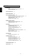
ENGLISH CONTENTS • Introduction READ THIS BEFORE OPERATING YOUR UNIT SAFETY INSTRUCTION | 3 • System Connections | 5 • Front Panel Controls | 14 | 2 • Universal Remote Controls | 16 OPERATING COMPONENTS WITH REMOTE CONTROL REMOTE CONTROL OPERATION RANGE | 19 LOADING BATTERIES | 19 ENTERING A SETUP CODE | 20 | 19 • ROOM 2 Remote Controls REMOTE CONTROL OPERATION RANGE LOADING BATTERIES | 22 | 22 • Operations LISTENING TO A PROGRAM SOURCE | 23 SURROUND SOUND | 26 ENJOYING SURROUND SOUND | 29 LISTE
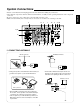
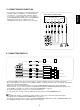
• Pleas be certain that this unit is unplugged from the AC outlet before making any connections. • Since different components often have different terminal names, carefully read the operating instructions of the component connected. • Be sure to observe the color coding when connecting audio and video cords. • Make connections firmly and correctly. If not, it can cause loss of sound, noise or damage to the unit. 3 11 7 1 13 8 9 10 4,11 6 5 4 2 3 5 12 1.
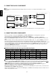
2. CONNECTING AUDIO COMPONENTS ENGLISH Note: • Do not connect the turntable with MC type cartridge directly. If you have it, use a separate head amplifier or set-up transformer. AUX CD recorder, MD recorder, etc. L AUDIO R IN L AUDIO R OUT TAPE MONITOR Tape deck, MD recorder, etc. AUDIO L IN R AUDIO L OUT R CD CD player, etc.
VIDEO 2 DVD player, DVD recorder, etc. Y CB CR COMPONENT OUT Y COMPONENT OUT CB AUDIO OUT R L AUDIO IN R L (COMPOSITE) VIDEO OUT IN CR S-VIDEO OUT IN AUDIO OUT R L AUDIO IN R L (COMPOSITE) VIDEO OUT IN S-VIDEO OUT IN • The jacks of VIDEO 1 / VIDEO 2 may also be connected to a DVD recorder or other digital video recording component. For details , refer to the operating instructions of the component to be connected.
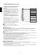
ENGLISH 4. CONNECTING DIGITAL INs and OUTs • The OPTICAL and the COAXIAL DIGITAL OUTs of the components that are connected to CD, AUX and VIDEO 1~ VIDEO 6 of this unit can be connected to these DIGITAL INs. • A digital input should be connected to the components such as a CD player, LD player, DVD player, etc. capable of outputting DTS Digital Surround, Dolby Digital or PCM format digital signals, etc.
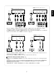
5. CONNECTING 8CH DIRECT INs • Use these jacks to connect the corresponding analog audio and video outputs of a DVD player or a external decoder , etc. that has 6 , 7 or 8 channel audio and video outputs. • In case of 6 or 7 channel outputs , do not connect both of the SURROUND BACK L and R inputs or the SURROUND BACK R input of this unit . (For details, refer to the operating instructions of the component to be connected. ) S-VIDEO OUT 8 CH DIRECT OUTs CENTER SUBWOOFER FRONT R L SURROUND SURR.
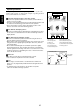
Speaker placement ENGLISH Ideal speaker placement varies depending on the size of your room and the wall coverings, etc. The typical example of speaker placement and recommendations are as follows : Front left and right speakers and center speaker • Place the front speakers with their front surfaces as flush with TV or monitor screen as possible. • Place the center speaker between the front left and right speakers and no further from the listening position than the front speakers.
7. CONNECTING SYSTEM CONTROL • Connect this jack to the DIGI LINK jack of the external Sherwood component that uses the DIGI LINK II or III remote control system. CD player Tape deck System control cord DVD player 8.
• The multi-room system kit(sold separately ) is essential for operation from a remote location . For information on the multi-room system kit, contact the Xantech corporation at 1-800-843-5465 or www.xantech.com. • IR IN jack allow you to control this unit from another room with the remote control unit. • To control this unit from another room with the remote control unit, connect the IR IN jack to the output of the connecting block.
• This unit incorporates USB as well as RS-232C terminal that may be used in the future to update the operating software so that it will be able to support new digital audio formats, external control by using an external device and the like. • Connect either USB or RS-232C terminal to your PC(You don’t need to do both). PC with USB or RS-232C port UPGRADE switch Notes : • Be sure to set the UPGRADE switch to “SVC”(service) before updating.
Front Panel Controls 14 ENGLISH 13 11 12 1 15 2 3 4 5 6 7 20 21 22 23 8 9 10 • To open the panel door, push gently on the lower third of the panel door. 16 24 25 17 18 26 27 19 28 29 30 1. POWER switch 2. STANDBY button/indicator 3. DECODING MODE button 4. STEREO button 5. DIGITAL/ANALOG button 6. PURE AUDIO button 7. VIDEO SELECTOR button 8. AUDIO SELECTOR button 9. TAPE MONITOR button 10. 8 CH DIRECT button 11. MASTER VOLUME CONTROL knob 12. MULTI CONTROL knob 13.
FLUORESCENT DISPLAY 2 3 4 5 6 7 DOLBY H DIGITAL EX VIRTUAL DIRECT AUTO L C R PCM PRO LOGIC MPEG PURE 3 8 DTS ES 96/24 NEO:6 Z SOUND TAPE MON STEREO ANALOG DIGITAL RE-MASTERING TUNED PRESET VIDEO SET 123456 R2 MUTE CINE-EQ MEMORY 19 20 21 22 AP-SW 23 SL SW SR LFE SB 11 10 12 1. CHANNEL indicators 2. PCM SIGNAL indicator 3. SURROUND MODE indicators 4. TAPE MONITOR indicator 5. DIRECT indicator 6. STEREO indicator 7. AUTO indicator 8. SLEEP indicator 9. VIDEO INPUT indicators 10.
ENGLISH Universal Remote Controls This universal remote control can operate not only this unit but also most popular brands of audio and video components such as CD players, DVD players, tape decks, TVs, VCRs, satellite receivers, cable boxes, etc. • To operate 8 components other than this unit, you should enter the setup code for each component. (For details, refer to “ENTERING A SETUP CODE” on page 20) • The numbered buttons on the remote control have different functions in different device modes.
FUNCTION TABLE of the NUMBERED BUTTONS. Device to be controlled Button symbol AUDIO 1("AUD1") AUDIO 2("AUD2") CD TAPE TV (for receiver, "001") (for receiver, "001") (for CD player, "001") (for tape deck, "001") (for TV, "001") POWER ON POWER ON POWER ON STANDBY STANDBY STANDBY STANDBY CHANNEL SELECTOR CHANNEL SELECTOR CH.
Continued Device to be controlled Button symbol DVD(for DVD player) V-768, etc.("001") VD-4106, etc.("091") VD-8300, etc.("116") POWER ON POWER POWER STANDBY - - - - DIGEST - - - - - - - VOLUME UP( - - VOLUME DOWN( ENGLISH POWER ON STANDBY CH.
1 2 3 REMOTE CONTROL OPERATION RANGE Enter the setup code of the components respectively, referring to “ENTERING A SETUP CODE” (page 20). • Use the remote control within a range of about 7 meters (23 feet) and angles of up to 30 degrees aiming at the remote sensor. Turn on the components you want to operate. Select the device on the main menu of the remote control corresponding to the component you want to operate. Example) When selecting “AUD 1” or “AUD 2” to operate this unit.
ENGLISH ENTERING A SETUP CODE • This remote control can control up to ten different components. • Before operating audio and video components using the remote control supplied with this unit, the setup code for each component should be entered. • For system remote control operation between Sherwood components, “001” was stored previously in the memory of each device such as “AUD 1” and “AUD 2” for this unit, “CD” for CD player, “TAPE” for tape deck , “TV” for TV and “DVD” for DVD player.
7 8 Confirm that it is the right code by selecting the SAVE. POWER ON STANDBY AUD 1 001 SAVE EXIT POWER ON STANDBY DOWN UP ENTER PAGE AUD 1 FAV MAIN 001 SAVE CH. SET CH/ VOL ADJUST MUTE DECODE DSP DSP EXIT For "001" : 0 0 1 DOWN RETURN UP STEREO 1 2 3 4 5 6 7 8 9 ENTER OSD/MENU DISP MI 0 ENT M2 M3 For "102" : 1 0 2 RNC-510 • Your component will be turned off(or on in case of this unit, etc.) when the right code is entered.
This remote control unit is an additional remote control unit for the ROOM 2 source playback only. • You can use the ROOM 2 functions with this remote control unit more conveniently in another room than with the universal remote control unit. REMOTE CONTROL OPERATION RANGE • Aim the ROOM 2 remote control(or the universal remote control) at the IR receiver installed in another room.(For details, refer to “CONNECTING MULTI-ROOM SYSTEM KIT” on page 12.
Notes : • Before operating this unit with the supplied remote control, refer to “ Universal Remote Controls” on page 16 for details about operation. • Before operating this unit, first set this unit as desired for optimum performance, doing the OSD menu setting procedures. (For details, refer to “OSD Menu Settings” on page 42.) LISTENING TO A PROGRAM SOURCE Before operation 3 • Enter the standby mode. Select the desired input source.
ENGLISH When CD, AUX or VIDEO 1~ VIDEO 6 is selected 4 Adjusting the tone (bass and treble) Select the tone mode as desired. 7 Select the digital or the analog input as desired. POWER ON STANDBY AUD2 SLEEP or D/A DIMM S.A/B ROOM2 SUR.B T.TON PURE OSD PARA.
Achieving higher purity of sound quality ENGLISH Compensating for edgy or shrill movie sound tracks POWER ON STANDBY AUD2 SLEEP or D/A DIMM S.A/B ROOM2 SUR.B T.TON PURE OSD PARA. PAGE1 • Only when playing program sources recorded in either analog stereo or 2 channel PCM format, the pure audio function can be selected. • “PURE” lights up and the stereo mode is automatically selected and all the video-related circuits as well as the digital processing circuits are turned off.
SURROUND SOUND ENGLISH • This unit incorporates a sophisticated Digital Signal Processor that allows you to create optimum sound quality and sound atmosphere in your personal Home Theater. Surround modes • DTS Neo : 6 Cinema This mode is optimum for playing movies. Decoding is performed with emphasis on separation performance to achieve the same atmosphere with 2-channel sources as with 6.1-channel sources.
Dolby Virtual Speaker This mode creates a virtual surround sound field using as few as two front speakers, allowing you to experience listening from 5.1 channel speakers. This mode is effective not only for 5.1 channel sources but also for stereo ( 2 channel ) sources. • Dolby Pro Logic IIx Movie When enjoying movies, this mode allows you to further enhance the cinematic quality by adding processing that emphasizes the sounds of the action special effects.
For your reference, the sound from each channel can be reproduced according to the surround modes as follows: Modes Channels FRONT L/R CENTER SURROUND L/R SURROUND BACK L/R SUBWOOFER ENGLISH DTS, DTS 96/24 DTS ES DISCRETE/MATRIX DTS NEO 6: CINEMA/MUSIC DOLBY DIGITAL DOLBY DIGITAL EX DOLBY PRO LOGIC IIx MOVIE/MUSIC DOLBY PRO LOGIC II MOVIE/MUSIC DOLBY VIRTUAL SPEAKER MPEG 4CH STEREO Other Surrounds STEREO 8 CH DIRECT (*): Depending on the subwoofer mode setting, the sound from the subwoofer channel m
• Surround sound effect will not work properly if the signal passes through a graphic equalizer. Please refer to your equalizer operating instructions for guidance on switching off (or defeating) the equalizer. Note: Before surround playback, first perform the SPEAKER SETUP procedure, etc. on the OSD menu for optimum performance. (For details, refer to “SETTING THE SPEAKER SETUP” on page 44.) Depending on the input digital signal format, select the desired decoding mode.
Continued ENGLISH When canceling the surround mode for normal stereo operation. POWER ON STANDBY PAGE • Depending on the signal format which is being input, either the stereo mode or the 2CH downmix mode is selected. • To cancel either the stereo mode or the 2 CH downmix mode, select the desired surround mode with using the MULTI CONTROL knob or DSP MODE UP/DOWN ( / ) buttons. FAV MAIN CH.
To listen in a Dolby Headphone mode • The Dolby Headphone function simulates 5.1 channel surround sound, which allows you to enjoy 5.1 channel surround sound through 2 channel headphones, just like listening from 5.1 channel speakers. Note : Only when the HEADPHONE SELECTOR button is set to the speaker off mode, the Dolby Headphone mode can be selected. • While listening with headphones, select the desired Dolby Headphone mode.
ENGLISH Adjusting each channel level with test tone • The volume level of each channel can be adjusted easily with the test tone function. Note: When speakers are switched off , the test tone function does not work. Enter the test tone mode. • The test tone will be heard from the speaker of each channel for 2 seconds as follows: 1 FL Front Left AUD2 SLEEP SL SR Front Right ( Surround Right SC) or ( Surround Left (Surround Center) BL BR) (Surr. Back Left Surr. Back Right) D/A DIMM S.
3 Repeat the above steps each channel level. and to adjust ENGLISH 2 Adjust the level of the selected channel as desired. POWER ON STANDBY PAGE FAV MAIN CH.
ENGLISH LISTENING TO RADIO BROADCASTS Select the desired band. Auto tuning 1 2 Select the tuner. POWER ON STANDBY AUD1 TUNER or VID2 T.MON VID3 AUX BAND VID1 CD VID4 PHONO FREQUENCY • Each time this button is pressed, the band is changed to FM or AM. • When pressing the BAND button without selecting the TUNER, the tuner will be selected automatically. VID5 PAGE1 Press the TUNING UP(+) or DOWN(-) button for more than 0.5 second. 3 + • Then “ AUTO” appears on the display.
2 • You can store up to 30 preferred stations in the memory. Press the (ENTER/) MEMORY button. POWER ON STANDBY Tune in the desired station with auto or manual tuning. 1 AUD2 or SCH,M E.TA PTY S E.PTY MEMO P.SCA TUNE+ PSET+ TUNE- PSET- PAGE2 Note • When performing manual presetting with the remote control, first be sure to turn off the OSD menu display. • “MEMORY” is flickering for several seconds. Select the desired preset number (1~30) and press the (ENTER/)MEMORY button.
Scanning preset stations in sequence ENGLISH Listening to FM stereo broadcasts • While listening to FM broadcasts. POWER ON STANDBY AUD2 • Each time this button is pressed, the FM mode changes as follows; SCH.M E.TA PTY S E.PTY MEMO P.SCA TUNE+ PSET+ TUNE- PSETPAGE2 Stereo mode : “STEREO” lights up. Mono mode : “STEREO” goes off.
• The analog signals from the 8 CH DIRECT inputs as well as the digital signals from DIGITAL inputs or USB can be heard but cannot be recorded. • The volume, channel level, tone(bass, treble) settings, etc. have no effect on the recording signals. Recording with TAPE MONITOR 1 2 Select the desired input as a recording source except TAPE MONITOR. 3 POWER ON STANDBY AUD1 TUNER or VID1 CD VID2 T.MON VID3 AUX VID4 PHONO • You can select “VID 6” on the page 2 of “AUD 1” on the remote control.
4 ENGLISH 3 Start recording on the component connected to VIDEO 1. Start play on the components connected to VIDEO 2 and CD respectively. • The audio signal from the CD and the video signal from the VIDEO 2 will be dubbed and you can enjoy them on the TV set and from the speakers. • When the VIDEO 2(/ROOM 2) IN/OUT jacks are connected to video recording component such as video deck, etc., in the same manner, recording with VIDEO 2 can be performed.
OTHER FUNCTIONS 2 Adjust the dynamic range as desired. ENGLISH Compressing the dynamic range (Dolby Digital sources only) • This function compresses the dynamic range of previously specified parts of the Dolby Digital sound track(with extremely high volume)to minimize the difference in volume between the specified and nonspecified parts. This makes it easy to hear all of the sound track when watching movies at night at low levels.
ENGLISH Entering a label 2 • This function can be operated on the input sources except TUNER, TAPE MONITOR and 8 CH DIRECT. 1 Press the LABEL button to enter the label input mode. Example ) When selecting VIDEO 1. Select the desired input source to enter its label. POWER ON STANDBY AUD1 TUNER or VID1 CD VID2 T.MON VID3 AUX VID4 PHONO 4 VID5 PAGE1 Confirm your selection. • You can select “VID 6” on the page 2 of “AUD 1” on the remote control. • Then the next digit will flicker.
• This function allows enjoying one source in the main room and playing another in a different room at the same time. • The analog signals from the 8 CH DIRECT inputs and TAPE MONITOR INs cannot be output from the VIDEO 2 / ROOM 2(audio) OUTs and the digital signals from the USB terminal cannot be output from the COAXIAL DIGITAL OUT, meaning no playback in a different room.
ENGLISH Using the OSD This unit incorporates an OSD(On-screen display) function to provide information about basic operation of this unit and to simplify the setup procedures. The OSD function uses a monitor TV connected to this unit as a display and has two kinds of display modes such as current status display and menu screen. Notes : • Any on-screen display shown on the monitor TV will not be recorded.
2 Select the desired menu using the CURSOR UP( )/DOWN( ) buttons. POWER ON STANDBY PAGE FAV MAIN CH. SET ENGLISH CH/ VOL ADJUST MUTE DECODE DSP DSP RETURN STEREO 1 2 4 5 7 8 3 6 9 OSD/MENU 3 DISP 0 ENT MI M2 M3 Confirm your selection. • The selected category or item will provide the needed setting details using the subsequent screens. POWER ON STANDBY PAGE FAV MAIN CH.
ENGLISH SETTING THE SPEAKER SETUP • After you have installed this unit and connected all the components, you first perform the speaker setup settings for the optimum sound acoustics according to your environment and speaker layout. • Even when you change speakers, speaker positions, or the layout of your listening environment, you should perform the speaker setup settings, too.
and until the speakers are all set to the desired mode. ENGLISH 4 Repeat the above steps When selecting the SPEAKER DISTANCE 1 Press the CURSOR UP( ENTER button. )/DOWN( ) buttons to select the SPEAKER DISTANCE, then press the POWER ON STANDBY SPEAKER DISTANCE PAGE UN I T : F L : 10 F C : 10 SURR . SURR . BL : 10 FAV MAIN CH.
ENGLISH When selecting the VIRTUAL SPEAKER SETUP 1 Press the CURSOR UP( the ENTER button. )/DOWN( ) buttons to select the VIRTUAL SPEAKER SETUP, then press POWER ON STANDBY VIRTUAL SPEAKER SETUP DOL B Y PAGE VS : Off FAV MAIN CH.
6 Press the CURSOR LEFT( )/RIGHT( ) buttons to select the desired mode. POWER ON STANDBY POWER ON STANDBY PAGE FAV MAIN CH. SET CH/ VOL ADJUST MUTE DECODE DSP PAGE DSP FAV MAIN RETURN STEREO CH.
ENGLISH When selecting the SUBWOOFER MODE 1 2 Press the CURSOR UP( )/DOWN( ) buttons to select the SUBWOOFER MODE. Press the CURSOR LEFT( )/RIGHT( ) buttons to select the desired mode. POWER ON STANDBY PAGE FAV MAIN CH. SET POWER ON STANDBY CH/ VOL ADJUST MUTE DECODE DSP DSP RETURN STEREO PAGE 1 2 4 5 7 8 FAV MAIN CH.
• Auto Speaker Setup lets you avoid troublesome listening-based speaker setup and achieve good surround sound. You should connect the supplied microphone to the SETUP MIC jack so that this receiver can analyze the information from a series of test tones emitted from speakers and can adjust the size, distance and sound level of each speaker automatically.
ENGLISH Continued 3 To confirm the results, press the CURSOR LEFT( )/RIGHT( ) buttons to select the “MEMORY”, then press the ENTER button. POWER ON STANDBY PAGE AUTO SPEAKER SETUP S T ART F L : 0 dB , L , 1 0 f F C : + 6 dB , S , 1 0 f F R : + 3 dB , L , 1 0 f S R : + 5 dB , S , 0 7 f B R : + 4 dB , S , 0 7 f B L : + 4 dB , S , 0 7 f S L : + 1 dB , S , 0 7 f S W : 1 5dB R E T U R N : B a c k E N TER : S e l e c FAV MAIN CH.
SETTING THE SYSTEM SETUP To assign the connected DIGITAL INs to the desired input sources respectively To adjust the tone as desired or to select the desired cinema EQ mode. To set the OSD AUTO DISPLAY mode as desired . To select a video input source To assign the connected COMPONENT VIDEO INs to the desired of VIDEO 1~6. To set the VIDEO 2 OUT mode as desired. To select the desired input source that uses the DC trigger 2 function. To select the desired digital re-mastering mode. D .
ENGLISH When selecting the TONE CONTROL 1 Press the CURSOR UP( button. )/DOWN( ) buttons to select the TONE CONTROL, then press the ENTER POWER ON STANDBY T ON E C O N T R O L C I N EMA PAGE EQ : Off : Off FAV MAIN CH. SET T ONE DEF E A T CH/ VOL ADJUST MUTE DECODE DSP DSP RETURN STEREO 1 2 4 5 7 3 6 RETURN: Ba ck 9 8 OSD/MENU DISP 0 ENT MI M2 M3 , :Se l e c t RNC-510 Note: • When the pure audio function is activated, the TONE CONTROL cannot be selected.
2 • When the OSD AUTO DISPLAY is set to On, the current status display overlaps the program image on the monitor TV and may interfere with your movie enjoyment. In such a case, set the OSD AUTO DISPLAY to Off. Press the CURSOR LEFT( )/RIGHT( ) buttons to select the desired mode. POWER ON STANDBY PAGE FAV MAIN CH. SET CH/ VOL ADJUST MUTE 1 DECODE Press the CURSOR UP( )/DOWN( ) buttons to select the OSD AUTO DISPLAY.
ENGLISH When selecting the COMPONENT VIDEO SETUP • You should assign the connected COMPONENT VIDEO INs to the desired of VIDEO 1~6. (For details, refer to “CONNECTING VIDEO COMPONENTS” on page 6~7.) 1 Press the CURSOR UP( the ENTER button. )/DOWN( ) buttons to select the COMPONENT VIDEO SETUP, then press POWER ON STANDBY C OM P ONE N T PAGE V V V V V V FAV MAIN CH.
Press the CURSOR LEFT( )/RIGHT( ) buttons to select the desired mode. 2 • When performing recording with the video recording component connected to VIDEO 2 (/ROOM 2) IN/OUT jacks, you should set the VIDEO 2 OUT to On and deactivate the ROOM 2 function. Note: When the ROOM 2 function is activated, ROOM 2 source playback will be performed regardless of the VIDEO 2 OUT setting. ENGLISH When selecting the VIDEO 2 OUT POWER ON STANDBY PAGE FAV MAIN CH.
ENGLISH Continued When the DC TRIGGER 2 mode is set to On 3 Press the CURSOR UP( )/DOWN( )/LEFT( )/RIGHT( ) buttons to select the desired input source that uses the DC trigger 2 function, then press the ENTER button. • Each time the CURSOR CONTROL buttons are pressed, “ ” is moved to the corresponding input source. When the ENTER button is pressed at the desired input source, “+” is marked it with.
• There may be a slight delay between the video and audio signals in case that some video playback equipments may process the video signals later than the audio signals due to signal processing procedure, etc.. Should this happen, you can adjust the A/V SYNC to synchronize sound with image. 1 Press the CURSOR UP( )/DOWN( ) buttons to select the A/V SYNC. POWER ON STANDBY PAGE FAV MAIN CH.
SETTING THE SURROUND SETUP ENGLISH S U R ROU N D SETUP DE COD I NG M O D E : A U T O S U R R OU N D M O D E : DO L B Y D I G I T A L E X + N ONE DY N A M I C R A N G E : 0 . 0 P L I I x M US I C P A R A M E T E R RETURN : B ack , : Se l ect To select the desired decoding mode. To select the desired surround mode. To select the desired Dolby surround mode. To adjust the dynamic range as desired. To adjust the PL IIx MUSIC PARAMETER as desired.
When the SURROUND MODE is selected Signal format being input Dolby Digital 5.1, Dolby Digital EX 6.
ENGLISH When selecting the PL IIx MUSIC PARAMETER(or the PL II MUSIC PARAMETER) Notes: • Depending on whether “S/B CH” is set to “None” or not, you can select either the Dolby Pro Logic II surround or the Dolby Pro Logic IIx surround and can adjust its parameters as desired only while listening in either the PL II MUSIC mode or the PL IIx MUSIC mode. (Refer to “When selecting the SPEAKER CONFIGURATION” on page 44.
CH LEVEL SETUP P R ESE T 1 : P R ESE T1 P R ESE T 2 : P R ESE T 2 CH L EVEL L F E L EVEL RETURN : B ac k C AL L TRIM C AL L TRIM TRIM TRIM , :Sel ect EN TE R : Ca l l To recall the channel levels memorized into preset memory or to memorize the channel levels adjusted in the CH LEVEL TRIM menu, etc. To memorize the adjusted channel levels into preset memory. To adjust the current channel levels as desired.
ENGLISH 2 Press the CURSOR UP( )/DOWN( ) buttons to select the desired channel. 3 POWER ON STANDBY PAGE POWER ON STANDBY PAGE FAV MAIN Press the CURSOR LEFT( )/RIGHT( ) buttons to adjust the level of the selected channel as desired. CH. SET CH/ CH/ VOL ADJUST ADJUST MUTE MUTE DECODE DECODE DSP DSP DSP RETURN 2 4 5 7 8 DSP RETURN STEREO 1 FAV MAIN CH.
When selecting the LFE LEVEL TRIM )/DOWN( ) buttons to select the LFE LEVEL TRIM, then press the ENTER POWER ON STANDBY LFE PAGE LEVEL TR IM FAV MAIN CH. SET CH/ VOL ADJUST MUTE DECODE DSP DSP RETURN STEREO 1 2 4 5 7 8 3 6 RETURN:Back 9 , : Select OSD/MENU DISP 0 ENT MI M2 M3 RNC-510 2 Press the CURSOR UP( )/DOWN( ) buttons to select the desired LFE level mode. POWER ON STANDBY • Each time these buttons are pressed, “ ” is moved to the corresponding LFE level mode.
ENGLISH SETTING THE ROOM2 FEED SETUP R OOM 2 F E E D V O L U M E MO D E ROOM2 F EE D T UNER CD AUX P HONO RETURN : B a c k S E T UP Variable : : Off V I DEO 1 V I DEO 2 V I DEO 3 V I DEO 4 V I DEO 5 V I DEO 6 , : S e l ect To select the desired volume mode. To select the desired ROOM 2 source. • The ROOM 2 function allows enjoying one source in the main room while playing another in a different room at the same time.
1 2 Press the CURSOR UP( )/DOWN( ) buttons to select the ROOM 2 FEED mode. Press the CURSOR LEFT( )/RIGHT( ) buttons to select the ROOM 2 FEED mode as desired. POWER ON STANDBY POWER ON STANDBY PAGE FAV MAIN CH. SET CH/ VOL ADJUST MUTE DECODE DSP PAGE FAV MAIN RETURN CH.
ENGLISH Troubleshooting Guide If a fault occurs, run through the table below before taking your unit for repair. If the fault persists, attempt to solve it by switching the unit off and on again. If this fails to resolve the situation, consult your dealer. Under no circumstances should you repair the unit yourself as this could invalidate the warranty! PROBLEM POSSIBLE CAUSE REMEDY No power • The AC input cord is disconnected. • Poor connection at AC wall outlet or the outlet is dead or off.
Specifications • Total harmonic distortion, output 1 V, 1 kHz | 0.05 % • Intermodulation distortion 60 Hz : 7 kHz = 4 : 1 SMPTE, 8 Ω, output 1 V | 0.09 % • Input sensitivity/impedance, output 1 V Phono (MM) | 2.5 mV/47 kΩ Line (CD, TAPE MONITOR, VIDEO) | 200 mV/47 kΩ • Signal to noise ratio, IHF “A” weighted Phono (MM) | 72 dB Line (CD, TAPE MONITOR, VIDEO) | 100 dB • Frequency response Phono (MM), RIAA, 30~20, 000Hz | 1.
P-965 A/V Tuner Pre Amplifier 5707-04747-001-1