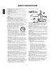
ENGLISH SAFETY INSTRUCTIONS 1. Read Instructions - All the safety and operating instructions should be read before the product is operated. 2. Retain instructions - The safety and operating instructions should be retained for future reference. 3. Heed Warnings - All warnings on the product and in the operating instructions should be adhered to. 4. Follow Instructions - All operating and use instructions should be followed. 5. Cleaning - Unplug this product from the wall outlet before cleaning.
Introduction This symbol is intended to alert the user to the presence of uninsulated "dangerous voltage" within the product's enclosure that may be of sufficient magnitude to constitute a risk of electric shock to persons. CAUTION : TO REDUCE THE RISK OF ELECTRIC SHOCK, DO NOT REMOVE COVER (OR BACK). NO USERSERVICEABLE PARTS INSIDE. REFER SERVICING TO QUALIFIED SERVICE PERSONNEL.
CONTENTS ENGLISH SAFETY INSTRUCTIONS | 2 Introduction • READ THIS BEFORE OPERATING YOUR UNIT | 3 System Connections | 5 Front Panel Controls | 13 Universal Remote Controls | 15 • OPERATING COMPONENTS WITH REMOTE CONTROL • REMOTE CONTROL OPERATION RANGE | 17 • LOADING BATTERIES | 17 • USING FUNCTIONS OF REMOTE CONTROL | 18 | 17 Operations • LISTENING TO A PROGRAM SOURCE | 21 • SURROUND SOUND | 23 • ENJOYING SURROUND SOUND | 25 • LISTENING TO RADIO BROADCASTS | 29 • RECORDING | 31 • DIGITAL AUDIO RECO
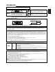
• Do not plug the AC input cord into the wall AC outlet until all connections are completed. • Be sure to observe the color coding when connecting audio, video and speaker cords. • Make connections firmly and correctly. If not, it can cause loss of sound, noise or damage to the receiver. AC INPUT 120V~60Hz 3.7A MODEL NO. This device complies with Part 15 of the FCC rules.
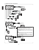
ENGLISH 2. CONNECTING VIDEO COMPONENTS • The jacks of VIDEO 1 may also be connected to a DVD recorder or other digital video recording component. For details, refer to the operating instructions of the component to be connected. • The jacks of VIDEO 2/VIDEO 3 can also be connected to an additional video component such as a cable TV tuner, an LD player or satellite system. • Connect the jacks of VIDEO 3 to the video component in the same way. Note : • When Sherwood DVD player such as V-768, etc.
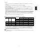
• There are three types of video jacks(COMPONENT, S-VIDEO, (composite) VIDEO) for connecting video components. Connect them to the corresponding video jacks according to their capability. • For your reference, the excellence in picture quality is as follows : "COMPONENT” > "S-VIDEO” > "(composite) VIDEO”. • When making COMPONENT VIDEO connections, connect "Y" to "Y", "PB/CB" to "CB"(or "B-Y", "PB") and "PR/CR" to "CR"(or "R-Y", "PR" ).
ENGLISH 3. CONNECTING AUDIO COMPONENTS • For ROOM 2 playback, the ROOM 2/TAPE OUT jacks can be connected to the amplifier, TV, etc. installed in another room instead of audio recording equipment such as a tape deck, an MD recorder, etc. (For details, refer to "CONNECTING ROOM 2 OUTs" on page 11.) • Depending on how to use the ROOM 2 /TAPE OUTs, you should assign these correctly. (For details, refer to "When selecting the OUT ASSIGN" on page 37.) 4.
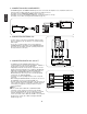
6. CONNECTING SYSTEM CONTROL ENGLISH • Connect this jack to the DIGI LINK jack of the external Sherwood component that uses the DIGI LINK II or III remote control system. 7. SUBWOOFER PREOUT connection • To emphasize the deep bass sounds, connect a powered subwoofer. 8. CONNECTING SPEAKERS • Be sure to connect speakers firmly and correctly according to the channel(left and right) and the polarity(+ and -).
ENGLISH Speaker placement Ideal speaker placement varies depending on the size of your room and the wall coverings, etc. The typical example of speaker placement and recommendations are as follows : Front left and right speakers and center speaker • Place the front speakers with their front surfaces as flush with TV or monitor screen as possible. • Place the center speaker between the front left and right speakers and no further from the listening position than the front speakers.
9. CONNECTING DC TRIGGER OUT ENGLISH • Connect a component to DC TRIGGER OUT jack that allows DC 12 V to turn on when a specific input source is selected. • For details, refer to the operating instructions of the components to be connected . • To link DC TRIGGER OUT with a specific input source, refer to "When selecting the DC TRIGGER" on page 41. Notes : • This output voltage (12 V d.c., 100mA ) is for (status) control only, it is not sufficient for drive capability.
• The multi-room system kit(sold separately ) is essential for operation from a remote location . For information on the multi-room system kit, contact the Xantech corporation at 1-800-843-5465 or www.xantech.com. • IR IN jack allows you to control this receiver from another room with the remote control unit. • To control this receiver from another room with the remote control unit, connect the IR IN jack to the output of the connecting block.
ENGLISH Front Panel Controls ROOM EQ auto setup 1. POWER switch 2. POWER ON/STANDBY button/indicator 3. VIDEO INPUT SELECTOR button 4. AUDIO INPUT SELECTOR button 5. EXTERNAL IN button 6. FM/AM button 7. MASTER VOLUME CONTROL knob 8. HEADPHONE jack 9. SPEAKER button/indicator 10. SURROUND MODE button 11. STEREO button 12. OSD SETUP button 13. CHANNEL LEVEL button 14. CONTROL UP/DOWN( / ) buttons 15. DIGITAL/ANALOG MODE button 16. ROOM 2 button 17. MEMORY/ENTER button 18. TUNING UP/DOWN( / ) buttons 19.
ENGLISH SETUP MIC JACK • To use Auto Setup function, connect the supplied microphone to the SETUP MIC jack.(For details, refer to "When selecting the AUTO SETUP" on page 43.) Notes: • Because the microphone for Auto Setup is designed for use with this receiver, do not use a microphone other than the one supplied with this receiver. • After you have completed the auto setup procedure, disconnect the microphone.
This universal remote control can operate not only this receiver but also most popular brands of audio and video components such as CD players, cassette decks, TVs, cable boxes, VCRs, DVD players, satellite receivers, etc. • To operate 7 components other than this receiver, you should enter the setup code for each component. (For details, refer to "USING FUNCTIONS OF REMOTE CONTROL" on page 18.
ENGLISH FUNCTION TABLE of the NUMBERED BUTTONS Notes: • Some functions for each component may not be available or may work differently. • Depending on other kinds of components that are available for each DEVICE button, some functions may not be available or may work differently, too. • For details about functions, refer to the operating instructions of each component.
1 2 3 REMOTE CONTROL OPERATION RANGE Enter the setup code for each component other than this receiver. For details, refer to "Entering a setup code" on page 18. • Use the remote control unit within a range of about 7 meters (23 feet) and angles of up to 30 degrees aiming at the remote sensor. Turn on the component you want to operate. ROOM EQ auto setup Press the DEVICE button on the remote control corresponding to the component you wish to operate.
ENGLISH USING FUNCTIONS OF REMOTE CONTROL • This remote control can control up to 8 different components. • Before operating audio and video components other than this receiver with using this remote control, the setup code for each component should be entered. • For system remote control operation, "000" was stored previously in the memory of the device button "CD" for Sherwood CD player, "DVD" for Sherwood DVD player and "AUX" for Sherwood tape deck respectively as its factory setup code.
Using a punch-through function CH.LEVEL CH.LEVEL CHANNEL CHANNEL ENTER ENTER • If removing is performed successfully, the LED will flicker twice. • When you want to remove either TV volume or TV channel punch-through, press and hold down both "TV" button and either "VOLUME " or "CHANNEL " button for more than 1 second. CH.LEVEL CH.LEVEL CHANNEL CHANNEL ENTER ENTER Removing all punch-through functions Press and hold down both "AUD" button and "D/A MODE" button for more than 1 second.
ENGLISH Programming a macro function 2 • The macro function enables you to program a series of button operations(up to 10) on this remote control into a single button. • You can store up to three separate macro command sequences into "M1", "M2" and "M3" buttons. Press and hold down both "ENTER" button and one of three NUMERIC buttons ("1"~"3") corresponding to "M1"~"M3" buttons for more than 1 second. Example) When programming a series of button operations into "M1" button.
Notes: • Before operating this receiver with the supplied remote control, refer to "Universal Remote Controls" on page 15 for details about operation. • Before operating this receiver, first set this unit as desired for optimum performance, doing the OSD menu setting procedures. (For details, refer to "OSD Menu Settings" on page 35.) LISTENING TO A PROGRAM SOURCE Select the desired input source. 3 Before operation • Enter the standby mode. • The POWER ON/STANDBY button lights up in amber.
ENGLISH When CD, VIDEO 1~3 is selected as an input source 4 Select the digital or analog input connected as desired. • Each time this button is pressed, the corresponding input is selected as follows ; A(nalog) o(ptical) 1 o(ptical) 2 c(oaxial) 1 c(oaxial) 2 CH.LEVEL CHANNEL ENTER Notes : • WhenTUNER, AUX, TAPE, EXTERNAL IN or VIDEO 4 is selected as an input source, the analog input is selected automatically.
SURROUND SOUND Surround modes • DTS Neo : 6 Cinema This mode is optimum for playing movies. Decoding is performed with emphasis on separation performance to achieve the same atmosphere with 2-channel sources as with 6.1-channel sources. DTS Digital Surround DTS Digital Surround(also called simply DTS) is a multichannel digital signal format which can handle higher data rates. Discs bearing the " " include the recording of up to 5.
ENGLISH Dolby Pro Logic IIx surround Dolby Pro Logic Dolby Pro Logic IIx decodes all stereo (2 channel ) and 5.1 channel sources and extends to 7.1channel surround playback. It delivers the most natural, full range and immersing 7.1 channel listening experience.
Notes: • Before surround playback, first perform the speaker setup procedure, etc. on the OSD menu for optimum performance. (For details, refer to "SETTING THE SPEAKER/ROOM EQ SETUP" on page 43.) • When playing digital signals from the Dolby Digital program source or selecting the surround mode such as Dolby Pro Logic II /Dolby Pro Logic IIx Music, Dolby Headphone, Dolby Virtual Speaker modes, you can adjust their parameters for optimum surround effect.
Continued To cancel the surround mode for stereo operation • Depending on the signal format which is being input, either the stereo mode or the 2CH downmix mode is selected. • To cancel either the stereo mode or the 2CH downmix mode, select the surround mode with using the MULTI CONTROL knob on the front panel or the SURROUND MODE UP/DOWN ( >/< ) buttons on the remote control. CH.
Adjusting the current channel level 1 ENGLISH • After adjusting each channel level with test tone, adjust the channel levels either according to the program sources or to suit your tastes. • You can adjust the current channel levels as desired. These adjusted levels are just memorized into user’s memory ("CAL"), not into preset memory("REF 1", "REF 2"). Press the CHANNEL LEVEL button. • Then the memory mode ("CAL" or "REF 1") is displayed for several seconds.
Memorizing the adjusted channel levels ENGLISH • You can memorize the adjusted channel levels into preset memory("REF 1", "REF 2") and recall the memorized whenever you want. 1 After performing the steps ~ in "Adjusting the current channel level" procedure on page 27, press the (MEMORY/) ENTER button. • The "1" of "REF 1" indication flickers for several seconds. CH.LEVEL CHANNEL ENTER 2 Select the desired one of REF 1 and REF 2. Confirm your selection. 3 CH.LEVEL CH.
LISTENING TO RADIO BROADCASTS 2 Select the tuner. 1 CH.LEVEL CHANNEL ENTER • Each time this button is pressed, the band changes as follows ; FM STereo ("ST" lights up) FM MONO AM MONO ("ST" goes off) • When FM stereo broadcasts are poor because of weak broadcast signals, select the FM mono mode to reduce the noise, then FM broadcasts are reproduced in monaural sound. • When pressing the FM/AM button without selecting the tuner, the tuner will be selected automatically.
Presetting radio stations ENGLISH • You can store up to 30 preferred stations in the memory. 1 Press the MEMORY/ENTER button. 2 Tune in the desired station with auto or manual tuning. • "MEM" is flickering for several seconds. 3 Select the desired preset number (1~30) and press the MEMORY/ENTER button. 4 Repeat the above steps memorize other stations. to to MEMORY BACKUP FUNCTION • The station has now been stored in the memory.
• The analog signals from the EXTERNAL INs as well as the digital signals from the coaxial or optical digital input can be heard but cannot be recorded. • When recording the analog signals from CD, VIDEO 1~3, be sure to select the analog input. (For details, refer to "When CD, VIDEO 1~3 is selected as an input source" on page 22.) • The volume and tone (bass, treble) settings have no effect on the recording signals. Start recording on the TAPE.
Start recording on the VIDEO 1. 4 ENGLISH 3 Start play on the VIDEO 2 and the CD respectively. • The audio signal from the CD and the video signal from the VIDEO 2 will be dubbed and you can enjoy them on the TV set and from the speakers. Note: Be sure to observe the order of the and .
Operating the sleep timer Adjusting the brightness of the fluorescent displays • The sleep timer allows the system to continue to operate for a specified period of time before automatically shutting off. • To set the receiver to automatically turn off after the specified period of time. CH.LEVEL CHANNEL ENTER CH.
ENGLISH ROOM 2 SOURCE PLAYBACK • This function allows enjoying one source in the main room and playing another in a different room at the same time. • When you connect the multi-room system kit to the IR IN jack of this receiver, you can control this receiver with the remote control unit in a different room. (For details, refer to "CONNECTING MULTI-ROOM SYSTEM KIT" on page 12.
• The OSD (On-Screen Display) menu is a setting menu that is displayed on the monitor TV and allows you to perform the setup procedures easily. In most situations, you will only need to set this once during the installation and layout of your home theater, and it rarely needs to be changed later. The OSD menu consists of 6 main menus ; system setup, input setup, speaker / room EQ setup, CH level setup, sound parameter and room 2 setup. These menus are then divided up into various sub-menus.
Confirm your selection. ENGLISH 3 When selecting the SYSTEM SETUP When selecting the INPUT SETUP When selecting the SPEAKER /ROOM EQ SETUP When selecting the SOUND PARAMETER When selecting the CH LEVEL SETUP When selecting the ROOM 2 SETUP • For the setting details, see page in • Adjust the setting(s) in each setting category to your preference. • When the OSD button is pressed on a sub-menu, the menu screen will be turned off.
• AMP ASSIGN : To assign the surround back channel's power amplifier to ROOM 2 for ROOM 2 playbak. • OUT ASSIGN : To assign the ROOM 2/TAPE OUTs to TAPE REC for analog audio recording. • SUBWOOFER MODE : To select the desired subwoofer mode. • TONE CONTROL : To adjust the tone (bass and treble) as desired. • CINEMA EQ : To select the desired cinema EQ mode. • MOMENTARY OSD : To turn on or off the OSD that shows the status corresponding to each operation momentarily.
Continued ENGLISH When selecting the SUBWOOFER MODE • "SW PLUS " mode is valid only when "FRONT" and "CENTER" are set to "LARGE" and "SUBWOOFER" is set to "YES" on the SPEAKER / ROOM EQ SETUP menu. (For details, refer to "SETTING THE SPEAKER / ROOM EQ SETUP" on page 43.) NORMAL : When the low frequency signals of channels set to "LARGE" are reproduced from those channels only.
When selecting the CINEMA EQ ON : To compensate for edgy or shrill movie sound tracks. Note : When the EXTERNAL IN is selected as an input source, the CINEMA EQ is automatically set to OFF. When selecting the MOMENTARY OSD ON : To turn on the OSD function that shows the status corresponding to each operation on this unit momentarily. OFF : To turn it off. Note : When outputting the component video signal from the MONITOR COMPONENT OUT jacks as it was input, the momentary OSD cannot be displayed.
SETTING THE INPUT SETUP ENGLISH • This menu allows you to make the various settings depending on how to use the input sources connected to this receiver. When selecting the items other than NAME 1 2 Press the CURSOR UP( )/DOWN( the ENTER button. ) buttons to select the desired input source, then press Press the CURSOR UP( )/DOWN( ) buttons to select the desired item. Example) When selecting the VIDEO 1 CH.
Continued When selecting the VIDEO MODE AUTO : When there are mutiple video input signals, the video input signals are detected and the video input signal to be output from the MONITOR OUTs is selected automatically in the following order : component video, S-video, composite video. COMPOSITE : The signal that is input into the (COMPOSITE) VIDEO jack is always played. The composite video input signal is up-converted and output from the S-VIDEO and COMPONENT MONITOR OUT jacks.
When selecting the NAME ENGLISH • You can give names to the input sources other than tuner. • Up to 8 characters can be entered for each name. 1 2 Press the CURSOR UP( )/DOWN( press the ENTER button. ) buttons to select the desired input source, then Example) When selecting the VIDEO 1 Press the CURSOR UP( )/DOWN( ) buttons to select the NAME, then press the ENTER button. • The first digit flickers. 3 Press the CURSOR LEFT( )/ RIGHT( buttons to select the desired digit.
• After you have installed this receiver and connected all the components, you should adjust the speaker settings for the optimum sound acoustics according to your environment and speaker layout. • Even when you change speakers, speaker positions, or the layout of your listening environment, you should adjust the speaker settings, too. • When performing the AUTO SETUP procedure, you need not perform the SPEAKER CONFIGURATION, SPEAKER DISTANCE, SPEAKER X-OVER and CH LEVEL SETUP procedures.
Continued ) buttons to select the AUTO SETUP, then press the Press the CURSOR UP( )/DOWN( button ) buttons to select the START, then press the ENTER ENGLISH 2 Press the CURSOR UP( )/DOWN( ENTER button. 3 When measurements at first position have been completed. • Loud test tones are output from each speaker and then if measurements at the first position have been completed, "SECOND POSITION" message will be displayed. Place the microphone on a flat level at the second main listening position.
Continued To check the results, press the ENTER button. • Then the results are memorized and the SPEAKER/ROOM EQ SETUP menu is displayed. • Check the results on each setup menu(SPEKER CONFIGURATION menu on page 45, SPEAKER DISTANCE menu on page 47, SPEAKER X-OVER menu on page 48 and CH LEVEL menu for "CALIBRATE" mode on page 50). • If the results are not satisfactory, you can retry the auto setup procedure or personalize your speaker setup and channel level setup by making the settings manually.
Continued ENGLISH 3 Press the CURSOR LEFT( )/ RIGHT( buttons to set the selected speaker as desired. • Depending on your speaker type, you can select one of these following speaker types. LARGE: Select this when connecting speakers that can fully reproduce sounds below crossover frequency. SMALL: Select this when connecting speakers that can not fully reproduce sounds below crossover frequency.
When selecting the SPEAKER DISTANCE 2 ) buttons to select the SPEAKER DISTANCE, then Press the CURSOR UP( )/DOWN( ) buttons to select the desired item. ENGLISH 1 Press the CURSOR UP( )/DOWN( press the ENTER button. Note : • You cannot select the speakers set to "NONE". CH.LEVEL CHANNEL ENTER 3 Press the CURSOR LEFT( )/RIGHT( When selecting the desired unit • You can select either METER or FEET. • Once a unit is selected, the distances are automatically changed in the selected unit.
When selecting the SPEAKER X-OVER ENGLISH • When speakers are set to "SMALL", be sure to set their crossover frequency correctly according to their frequency characteristics. 1 2 Press the CURSOR UP( )/DOWN( the ENTER button. ) buttons to select the SPEAKER X-OVER, then press Press the CURSOR UP( )/DOWN( ) buttons to select the desired speaker. Note : • You cannot select the subwoofer and the speakers set to "NONE". CH.
• The room EQ is a kind of room equalizer for your speakers. According to the acoustic characteristics of your room measured by the auto setup, the room EQ automatically adjusts the frequency response of speakers. • If you use different brands or sizes of speakers for some channels or have a room with unique acoustic characteristics, such as walls, furniture, and the dimensions or the shape of the room, we recommend using the room EQ.
SETTING THE CH LEVEL SETUP ENGLISH Memory mode Note : • Depending on the speaker settings("NONE", etc.), some channels cannot be selected. Adjusting the current channel level • You can adjust the current channel levels as desired. These adjusted levels are just memorized into user’s memory("CALIBRATE"), not into preset memory("REF 1", "REF 2") • After adjusting each channel level with test tone, adjust the channel levels either according to the program sources or to suit your tastes.
Memorizing the adjusted channel levels 1 ENGLISH • You can memorize the adjusted channel levels into preset memory("REF 1", "REF 2") and recall the memorized whenever you want. After performing the steps ~ in "Adjusting the current channel level" procedure on page 50, press the CURSOR UP( )/DOWN( ) buttons to select the MODE(memory mode), then press the ENTER button. • The "REF 1" indication flickers. 2 Press the CURSOR LEFT( )/RIGHT( then press the ENTER button.
SETTING THE SOUND PARAMETER ENGLISH • NIGHT MODE : To adjust the dynamic range compression that makes faint sound easier to hear at low volume levels. • DOLBY PLII MUSIC : To adjust the various surround parameters for optimum surround effect. • DOLBY HEADPHONE : To select the desired listening mode for each Dolby Headphone mode. • DOLBY VIRTUAL : To select the speaker layout to be used actually for each Dolby Virtual Speaker mode.
• You can adjust the various surround parameters for optimum surround effect. Note: • The parameter settings are valid only when listening in either Dolby Pro Logic II Music mode or the Dolby Pro Logic IIx Music mode. 1 2 Press the CURSOR UP( )/DOWN( the ENTER button. ) buttons to select the DOLBY PLII MUSIC, then press Press the CURSOR UP( )/DOWN( ) buttons to select the desired parameter. CH.
ENGLISH When selecting the DOLBY HEADPHONE • You can select the desired listening mode for each Dolby Headphone mode. Note: • You can select the desired listening mode only when playing analog stereo, PCM 2 channel or Dolby Digital 2 channel source. 1 2 Press the CURSOR UP( )/DOWN( press the ENTER button. ) buttons to select the DOLBY HEADPHONE, then Press the CURSOR UP( )/DOWN( ) buttons to select the desired Dolby Headphone mode. CH.
• You can select the speaker layout to be used actually for each Dolby Virtual Speaker mode. Note: • The speaker layout settings are valid only when listening in a Dolby Virtual Speaker mode. 1 2 Press the CURSOR UP( )/DOWN( the ENTER button. ) buttons to select the DOLBY VIRTUAL, then press Press the CURSOR UP( )/DOWN( ) buttons to select the desired Dolby Virtual Speaker mode. CH.LEVEL CHANNEL ENTER 3 Press the CURSOR LEFT( )/RIGHT( ) buttons to select the desired speaker layout.
SETTING THE ROOM 2 SETUP ENGLISH • The ROOM 2 function allows enjoying one source in the main room while playing another in a different room at the same time. • ROOM 2 : To turn on or off the ROOM 2 function. • INPUT : To select the desired ROOM 2 source. • VOLUME : To adjust the volume on the power amplifier assigned to ROOM 2. Notes: • The analog signals from the EXTERNAL INs and the digital signals cannot be output to the different room, meaning no playback in a different room.
If a fault occurs, run through the table below before taking your receiver for repair. If the fault persists, attempt to solve it by switching the receiver off and on again. If this fails to resolve the situation, consult your dealer. Under no circumstances should you attempt to repair the receiver yourself. This could void the warranty. PROBLEM POSSIBLE CAUSE REMEDY No power • The AC input cord is disconnected. • Poor connection at AC wall outlet or the outlet is dead or off. • Connect cord securely.
ENGLISH Specifications AMPLIFIER SECTION • Power output, stereo mode, 6 Ω, THD 0.2 %, 40 Hz~20 kHz | 2 100 W • Total harmonic distortion, 6 Ω, 95 W, 1 kHz | 0.05% • Intermodulation distortion 60 Hz : 7 kHz= 4 : 1 SMPTE, 6 Ω, 95 W | 0.1% • Input sensitivity/impedance Line (CD, TAPE, VIDEO) | 200 mV/47kΩ • Signal to noise ratio, IHF "A" weighted Line (CD, TAPE, VIDEO) | 95 dB • Frequency response Line (CD, TAPE, VIDEO), 20 Hz~55 kHz | +0, -3 dB • Output level ROOM 2/TAPE OUT, 2.
Setup Code Table AOC Admiral Aiko Akai Alaron Ambassador America Action Ampro Anam Audiovox Baysonic Belcor Bell & Howell Bradford Brockwood Broksonic CXC Candle Carnivale Carver Celebrity Cineral Citizen Concerto Contec Craig Crosley Crown Curtis Mathes Daewoo Daytron Denon Dumont Dwin Electroband Emerson Envision Fisher Fujitsu Funai Futuretech GE Gibralter 005 041 014 005 026 024 027 043 027 030 027 003 019 027 003 028 027 005 005 010 050 030 012 011 027 027 010 027 007 012 022 030 003 016 002 044 050
ENGLISH Pilot Pioneer Portland Prism Proscan Proton Pulsar Quasar RCA Radio Shack Realistic Runco SSS Sampo Samsung Samsux Sansei Sansui Sanyo Scimitsu Scotch Scott Sears Semivox Semp Sharp Sherwood Shogun Signature Sony Soundesign Squareview Starlite Supreme Sylvania Symphonic TMK Tandy Technics Technoi Ace Techwood Teknika Telefunken Toshiba Totevision Vector Research Victor Vidikron 005 022 003 008 007 025 002 008 007 037 007 003 019 011 002 027 005 012 006 030 031 019 003 025 028 007 011 027 020 041 0
Minolta Mitsubishi Motorola Multitech NEC Nikko Noblex Olympus Opimus Orion Panasonic Penny Pentax Philco Philips Pilot Pioneer Profitronic Proscan Protec Pulsar Quarter Quartz Quasar RCA Radio Shack Radix Randex 011 000 008 014 026 005 015 014 004 005 000 015 004 023 023 023 025 004 023 004 005 004 004 000 008 027 004 000 017 005 023 004 005 031 020 004 004 008 004 004 005 014 023 013 015 007 011 011 004 013 000 005 005 Realistic 008 026 Runco STS Samsung Sanky Sansui Sanyo Scott Sears 026 025 026 005
ENGLISH Magnin Memorex Mitsubishi Orion Panasonic Penney Quasar RCA Sansui Sanyo Sear Sharp Sony Symphonic Zenith 023 005 028 (TV use 025) 027 (TV use 041) 001 004 (TV use 008) 028 (TV use 042) 004 (TV use 008) 023 028 (TV use 042) 004 (TV use 008) 028 (TV use 042) 013 (TV use 012) 004 (TV use 008) 027 (TV use 041) 000 023 000 005 027 (TV use 041) 002 (TV use 000) 000 000 DVD Harman/Kardon JVC Kenwood Megavox Mitsubishi Onkyo Panasonic Philips Pioneer Proscan RCA Samsung Sherwood Sony Technics Theta Digi
010 010 015 014 007 000 010 018 007 153 015 000 022 014 AUX-LD 026 Denon Mitsubishi NAD Pioneer Sony 008 008 001 009 009 General Instrument HTS Hitachi Hughes Net.
ENGLISH AUX-HOME AUTOMATION GE Lutron One For All Radio Shack Security System Universal X10 X10 Kenwood Krell LXI Linn MCS MTC Megavox Marantz Mission NSM Nikko Onkyo Opimus 043 044 042 043 042 042 042 AUX-DBS Awia Fisher Harman/Kardon JBL JVC Jerrold RCA Scientific Artlanta Sony Starcom 045 005 046 046 047 031 006 032 045 031 059 Panasonic Parasound Philips Pioneer Proton QED Quasar RCA Realistic Rotel SAE Sansui Sanyo Scott Sears Sharp Sherwood 029 AUX-ACCESSARY Archer GC Electronics Jebsee Rabbi