Introduction READ THIS BEFORE OPERATING YOUR UNIT ENGLISH This symbol is intended to alert the user to the presence of uninsulated "dangerous voltage" within the product's enclosure that may be of sufficient magnitude to constitute a risk of electric shock to persons. CAUTION : TO REDUCE THE RISK OF ELECTRIC SHOCK, DO NOT REMOVE COVER (OR BACK). NO USER-SERVICEABLE PARTS INSIDE. REFER SERVICING TO QUALIFIED SERVICE PERSONNEL.
• Introduction READ THIS BEFORE OPERATING YOUR UNIT . . . . . . . . . . . . . . . . . . . . . . . . . . . . . . . 2 • System Connections . . . . . . . . . . . . . . . . . . . . . . . . . . . . . . . . . . . . . . . . . . . . . . . . . . . . . . . . . . 4 • Front Panel Controls . . . . . . . . . . . . . . . . . . . . . . . . . . . . . . . . . . . . . . . . . . . . . . . . . . . . . . . . . 15 • Universal Remote Controls . . . . . . . . . . . . . . . . . . . . . . . . . . . . . . . . . . . . . . . . . . . . .
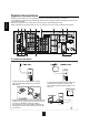
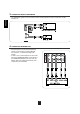
ENGLISH System Connections • Please be certain that this unit is unplugged from the AC outlet before making any connections. • Since different components often have different terminal names, carefully read the operating instructions of the component connected. • Be sure to observe the color coding when connecting audio, video and speaker cords. • Make connections firmly and correctly. If not, it can cause loss of sound, noise or damage to the receiver. 1 11 5 4 9 10 6 3 8 8 7 2 8 13 12 1.
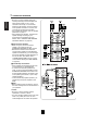
• The jacks of VIDEO 1 may also be connected to a DVD recorder or other digital video recording component. For details, refer to the operating instructions of the component to be connected. • The jacks of VIDEO 2/VIDEO 3 can also be connected to an additional video component such as a cable TV tuner or satellite system. • Connect the jacks of VIDEO 3 to the video component in the same way. HDMI (High Definition Multimedia Interface) connection : (*1) • You can connect the source component (DVD player, etc.
ENGLISH Continued Notes : • For stable signal transfer, we recommend using HDMI cords that are a maximum of 5 meters in length. • Among the components that support HDMI, some components can control other components via the HDMI connector. However, this unit cannot be controlled by another component via the HDMI connector. • The audio signals from the HDMI connector (including the sampling frequency and bit length) may be limited by the component that is connected.
Notes : • When the VIDEO MODE is set to "AUTO" or "HDMI", if the 576i ~ 1080i video signals are input into the HDMI IN connector, the HDMI video signals are output from the HDMI MONITOR OUT only. • When the VIDEO MODE is set to "AUTO" or "COMPONENT" and no video signals are input into the HDMI IN, if 576i video signals are input into the COMPONENT INs, the component video signals are output from the MONITOR OUTs.
3. CONNECTING AUDIO COMPONENTS ENGLISH • The TAPE IN/OUT jacks can be connected to audio recording equipment such as a tape deck, an MD recorder, etc. 4. CONNECTING EXTERNAL INS • Use these jacks to connect the corresponding outputs of a DVD player or external decoder, etc. that has 6, 7 or 8 channel analog audio outputs. • In case of 6 or 7 channel outputs, do not connect both of the SURROUND BACK L and R inputs or the SURROUND BACK R input of this unit.
• The OPTICAL and the COAXIAL DIGITAL OUTs of the components that are connected to this unit can be connected to these DIGITAL INs. • A digital input should be connected to the components such as a CD player, DVD player, etc. capable of outputting DTS Digital Surround, Dolby Digital or PCM format digital signals, etc. • If the component with OPTICAL IN jack is connected to the OPTICAL OUT jack of this unit, you can record the high quality sound of CDs, etc. without degradation.
ENGLISH 7. CONNECTING SPEAKERS • Be sure to connect speakers firmly and correctly according to the channel(left and right) and the polarity (+ and -). If the connections are faulty, no sound will be heard from the speakers, and if the polarity of the speaker connection is incorrect, the sound will be unnatural and lack bass. • For installing the speakers, refer to "Speaker placement" on page 11.
Speaker placement ENGLISH Ideal speaker placement varies depending on the size of your room and the wall coverings, etc. The typical example of speaker placement and recommendations are as follows : ■Front left and right speakers and center speaker • Place the front speakers with their front surfaces as flush with TV or monitor screen as possible. • Place the center speaker between the front left and right speakers and no further from the listening position than the front speakers.
ENGLISH 8. CONNECTING ROOM 2 OUTS • ROOM 2 playback feature allows you to play a different program source in another room as well as one source in the main room at the same time. • For ROOM 2 playback, connect the ROOM 2 OUT jacks to the amplifier, TV, etc. installed in another room, or connect the ROOM 2 speaker terminals to the speakers.
• The multi-room system kit(sold separately ) is essential for operation from a remote location . For information on the multi-room system kit, contact the Xantech corporation at 1-800-843-5465 or www.xantech.com. • IR IN jack allows you to control this receiver from another room with the remote control unit. • To control this receiver from another room with the remote control unit, connect the IR IN jack to the output of the connecting block.
ENGLISH 11. CONNECTING PC FOR UPGRADES • This receiver incorporates USB as well as RS-232C terminal that may be used in the future to update the operating software so that it will be able to support new digital audio formats, external control by using an external device and the like. • Connect either USB or RS-232C terminal to your PC (you don't need to do both).
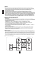
ENGLISH Front Panel Controls 1. POWER switch 2. POWER ON/STANDBY button/indicator 3. VIDEO INPUT SELECTOR button 4. AUDIO INPUT SELECTOR button 5. EXTERNAL IN button 6. TUNER button 7. AUDIO ASSIGN button 8. MASTER VOLUME CONTROL knob 9. HEADPHONE jack 10. SPEAKER button 11. PURE AUDIO button 12. SURROUND MODE button 13. STEREO button 14. SETUP button 15. CHANNEL LEVEL button 16. CONTROL UP(▲)/DOWN(▼) buttons 17. ROOM 2 button 18. MEMORY/ENTER button 19. TUNING UP(+)/DOWN(-) buttons 20.
ENGLISH SETUP MIC JACK • To use Auto Setup function, connect the supplied microphone to the SETUP MIC jack.(For details, refer to "When selecting the AUTO SETUP" on page 58.) Notes: • Because the microphone for Auto Setup is designed for use with this receiver, do not use a microphone other than the one supplied with this receiver. • After you have completed the auto setup procedure, disconnect the microphone.
This universal remote control can operate not only this receiver but also most popular brands of audio and video components such as CD players, tape decks, TVs, cable boxes, VCRs, satellite receivers, DVD players, etc. • To operate 7 components other than this receiver, you should enter the setup code for each component. (For details, refer to "USING FUNCTIONS OF REMOTE CONTROL" on page 20.) • The numbered buttons on the remote control have different functions in different device modes.
ENGLISH FUNCTION TABLE of the NUMBERED BUTTONS. Notes : • Some functions for each component may not be available or may work differently. • Depending on other kinds of components that are available for each DEVICE button, some functions may not be available or may work differently, too. • For details about functions, refer to the operating instructions of each component.
1. Enter the setup code for each REMOTE CONTROL OPERATION RANGE • Use the remote control within a range of about 7 meters (23 feet) and angles of up to 30 degrees aiming at the remote sensor. component other than this receiver. For details, refer to "Entering a setup code" on page 20. 2. Turn on the component you want to operate. 3. Press the DEVICE button on the remote control corresponding to the component you wish to operate. 4.
ENGLISH USING FUNCTIONS OF REMOTE CONTROL • This remote control can control up to 8 different components. • Before operating audio and video components other than this receiver with using this remote control, the setup code for each component should be entered.
6. Operate the component using the corresponding 3. While "PRESET" is displayed, search a setup function buttons. code, aiming the remote control at the remote sensor on the component. ENGLISH • If any of buttons fails to operate as they should, start from the step 1 again to enter the correct setup code. Note : • Manufacturers may use different setup codes for the same product category.
4. While "SEL" is flickering, on this remote control, ENGLISH Programming the commands from other remote controls (LEARNING mode) press the button corresponding to the function to be learned. • If the setup codes are not available for your component or you want to program a missing or special function into one button of a device, the learning function enables this remote control to learn the commands from other remote controls.
Erasing all the commands programmed under a device mode 1. Perform the steps 3 and 4 in "Entering a setup 1. Perform the steps 3 and 4 in "Entering a setup code" procedure on page 20 to select the deleting mode ("DELETE"). code" procedure on page 20 to select the deleting mode ("DELETE"). • Then "BTTN" is displayed on the LCD screen for several seconds. • Then "BTTN" is displayed on the LCD screen for several seconds. 2. While "BTTN" is displayed, press the CURSOR 2.
ENGLISH Programming a macro function • The macro function enables you to program a series of button operations(up to 15) on this remote control into a single button. • You can store up to three separate macro command sequences into "M1", "M2" and "M3" buttons. 3. While "SEL" is flickering, press the operation buttons you want to program in order. Example: When playing a DVD on the DVD player connected to VIDEO 2 jacks of this receiver. ①. Press "AUDIO" button to control this receiver. ②.
Operating a macro function • Aim the remote control at the REMOTE SENSORs of the components to be controlled and press the MACRO button you want. Example : When pressing "M1" button. UP(▲)/DOWN(▼) buttons to select the desired punch-through mode, then press the ENTER button. Notes: • The codes programmed into a MACRO button will be transmitted at an interval of 0.5 seconds. However, some components may not be able to complete one operation in 0.5 seconds and may miss the next code.
Continued Operating a punch-through function ENGLISH 3. While the device is displayed, press the • While this remote control is set to control a master device, aim the remote control at the REMOTE SENSOR of the punch-through device and press the desired button of the programmed punch-through controls. Example: When pressing "PLAY (▶)" button. CURSOR UP(▲)/DOWN(▼) buttons to select the desired punch-through device, then press the ENTER button.
Continued 3. While the device is displayed, press the 2. While "VOL" is displayed, press the CURSOR UP(▲)/DOWN(▼) buttons to select the all punch-through deleting mode ("DELETE"). ENGLISH CURSOR UP(▲)/DOWN(▼) buttons to select the one punch-through deleting mode ("DELETE"), then press the ENTER button.
ENGLISH ROOM 2 Remote Controls This remote control unit is an additional remote control unit for the ROOM 2 source playback only. • You can use the ROOM 2 functions with this remote control unit more conveniently in another room than with the universal remote control unit. • For details on ROOM 2 operation, refer to "ROOM 2 SOURCE PLAYBACK" on page 45. REMOTE CONTROL OPERATION RANGE • Aim the ROOM 2 remote control(or the universal remote control) at the IR receiver installed in another room.
Notes: • Before operating this receiver with the supplied remote control, refer to "Universal Remote Controls" on page 17 for details about operation. • Before operating this receiver, first set this unit as desired for optimum performance, doing the OSD menu setting procedures. (For details, refer to "OSD Menu Settings" on page 47.) LISTENING TO A PROGRAM SOURCE 3. Select the desired input source. Before operation • Enter the standby mode. • The POWER ON/STANDBY button lights up amber.
6. Operate the selected component for playback. ENGLISH When CD, AUX, VIDEO 1~ 4 is selected as an input source • When playing back the program sources with surround sound, refer to "ENJOYING SURROUND SOUND" on page 34. • If the AUDIO MODE is set to the mode other than "DIGITAL" for the corresponding input source on the INPUT SETUP menu, you cannot hear the sound from the selected digital input. (For details, refer to "SETTING THE INPUT SETUP" on page 53.) 7. Adjust the (overall) volume. 4.
Listening with headphones ENGLISH Achieving higher purity of sound quality • The PURE AUDIO indicator lights up, the fluorescent display goes off and all the videorelated circuits are turned off, meaning no video signal transfer. • When the pure audio is activated, the optimum surround mode (or stereo mode, etc.) will be automatically selected depending on the signal format being input. • Press this button again to cancel the pure audio function. • Ensure that the SPEAKER button is set to off.
SURROUND SOUND ENGLISH • This receiver incorporates a sophisticated Digital Signal Processor that allows you to create optimum sound quality and sound atmosphere in your personal Home Theater. Surround modes ■DTS Digital Surround ■Dolby Digital DTS Digital Surround(also called simply DTS) supports up to 5.1 discrete channels and uses less compression for high fidelity reproduction. Use it with DVDs and CDs bearing the DTS logo.
under the US and foreign patents pending and other related technology owned by Neural Audio Corporation. ■Dolby Virtual Speaker This mode creates a virtual surround sound field using as few as two front speakers, allowing you to experience listening from 5.1 channel speakers. This mode is effective not only for 5.1 channel sources but also for 2 channel sources.
ENGLISH ENJOYING SURROUND SOUND Notes: • Before surround playback, first perform the speaker setup procedure, etc. on the OSD menu for optimum performance. (For details, refer to "SETTING THE SPEAKER/ROOM EQ SETUP" on page 58.) • When playing digital signals from the Dolby Digital program source or selecting the surround mode such as Dolby Pro Logic II /Dolby Pro Logic IIx Music, Dolby Headphone, Dolby Virtual Speaker modes, you can adjust their parameters for optimum surround effect.
Continued • Depending on the signal format which is being input, either the stereo mode or the 2CH downmix mode is selected. • To cancel either the stereo mode or the 2CH downmix mode, select the surround mode with using the MULTI CONTROL knob on the front panel or the SURROUND MODE UP/DOWN ( >/< ) buttons on the remote control. 2CH downmix mode • This mode allows the multi-channel signals encoded in DTS or Dolby Digital format, etc.
ENGLISH Adjusting the current channel level • After adjusting each channel level with test tone, adjust the channel levels either according to the program sources or to suit your tastes. • You can adjust the current channel levels as desired. These adjusted levels are just memorized into user’s memory ("CALIBRATE"), not into preset memory("REFERENCE 1", "REFERENCE 2"). 1. Press the CHANNEL LEVEL button. 3. Adjust the level of the selected channel as desired.
Recalling the memorized channel levels Memorizing the adjusted channel levels • You can memorize the adjusted channel levels into preset memory("REFERENCE 1", "REFERENCE 2") and recall the memorized whenever you want. ENGLISH 1. Press the CHANNEL LEVEL button. 1. After performing the steps 1~4 in "Adjusting the current channel level" procedure on page 36, press the (MEMORY/)ENTER button. • "REFERENCE 1" (or "CALIBRATE") is displayed for several seconds.
LISTENING TO RADIO BROADCASTS Manual tuning ENGLISH Auto tuning • Manual tuning is useful when you already know the frequency of the desired station. • After selecting the desired band, press the TUNING UP(+)/DOWN(-) buttons repeatedly until the right frequency has been reached. 1. Select the desired band. Auto presetting • Each time this button is pressed, the band changes as follows : • Auto presetting function automatically searches for FM stations only and store them in the memory.
Manual presetting Tuning to preset stations • After selecting the tuner as an input source, select the desired preset number. ENGLISH • You can store up to 30 preferred stations in the memory. 1. Tune in the desired station with auto or manual tuning. 2. Press the MEMORY/ENTER button. Scanning preset stations in sequence • "MEMORY" is flickering for several seconds. 3. Select the desired preset number (1~30) and press the MEMORY/ENTER button.
RDS Tuner(Regional Option for some countries in Europe, etc.) ENGLISH LISTENING TO RDS BROADCASTS(FM ONLY) RDS(Radio Data System) is a method for sending information signals together with the transmitter signals. Your tuner is capable of translating these signals and putting the information on the display. These codes contain the following information. Program Service name(PS), A list of Program Types(PTY), Traffic Announcement(TA), Clock Time(CT), Radio Text(RT).
PTY search • Use this function to automatically search and receive the stations broadcasting the desired program type. ENGLISH 3. While displaying the desired program type. 1. In the FM mode, select the PTY search mode. • The tuner automatically searches a station offering PTY services. • If no station is found, "NO PROGRAM" is displayed. • "PTY SEARCH" is displayed. 2. While displaying "PTY SEARCH", select the DISPLAY desired program type.
ENGLISH RECORDING • The analog signals from the EXTERNAL INs as well as the digital signals from the HDMI IN, the OPTICAL or the COAXIAL DIGITAL IN can be heard but cannot be recorded. • When recording the analog signals from CD, AUX, VIDEO 1~4, be sure to select "ANALOG" for the AUDIO MODE. (For details, refer to "When selecting the AUDIO MODE" on page 55.) • When recording the video signals from VIDEO 2~4, be sure to select "COMPOSITE" or "S-VIDEO" for the VIDEO MODE.
DIGITAL AUDIO RECORDING WITH MD RECORDER 2. For digital recording, select the digital input as • Only when the OPTICAL DIGITAL OUT of this receiver is connected to the OPTICAL DIGITAL IN of the MD recorder or CD recorder, you can enjoy high-quality sound of digital recording without converting the original signals. Refer to "CONNECTING VIDEO COMPONENTS", "CONNECTING AUDIO COMPONENTS" and "CONNECTING DIGITAL INS AND OUT" on pages 5 ~9 and the operating instructions of the MD recorder or CD recorder.
OTHER FUNCTIONS ENGLISH Operating the sleep timer Displaying the audio information • The sleep timer allows the system to continue to operate for a specified period of time before automatically shutting off. • To set the receiver to automatically turn off after the specified period of time. • You can check the audio information on the input source on your monitor TV.
• This function allows enjoying one source in the main room and playing another in a different room at the same time. • When you connect the multi-room system kit to the IR IN jack of this receiver, you can control this receiver with not only the universal remote control unit but also the ROOM 2 remote control unit in a different room, too. (For details, refer to "CONNECTING MULTI-ROOM SYSTEM KIT" on page 13 and "ROOM 2 Remote Controls" on page 28.
Continued When using the buttons on the front panel 1. Press the ROOM 2 button to enter the ROOM 2 mode. ENGLISH 3. Set the selected mode as desired. • ROOM 2 ~ is displayed for several seconds. • When the ROOM 2 setting mode disappears, press the ROOM 2 button again. ■When selecting the ROOM 2 mode. ON : To turn on the ROOM 2 function. (" " lights up.) OFF : To turn it off. (" " or " " goes off depending on the AMP ASSIGN setting.) 2. Select the desired mode while displaying the ROOM 2 setting mode.
• The OSD (On-Screen Display) menu is a setting menu that is displayed on the monitor TV and allows you to perform the setup procedures easily. In most situations, you will only need to set this once during the installation and layout of your home theater, and it rarely needs to be changed later. The OSD menu consists of 6 main menus ; system setup, input setup, speaker / room EQ setup, CH level setup, sound parameter and multi room setup. These menus are then divided up into various sub-menus.
ENGLISH 3. Confirm your selection. When selecting the SYSTEM SETUP When selecting the INPUT SETUP 49 53 When selecting the SPEAKER /ROOM EQ SETUP When selecting the CH LEVEL SETUP 58 64 When selecting the SOUND PARAMETER When selecting the MULTI ROOM SETUP 66 70 • For the setting details, see page in ⇨. • Adjust the setting(s) in each setting category to your preference. • When the SETUP button is pressed on a sub-menu, the menu screen will be turned off.
• AMP ASSIGN : To assign the surround back channels' power amplifier correctly depending on how to use the speakers. • SUBWOOFER MODE : To select the desired subwoofer mode. • HDMI AUDIO OUT : To output the digital audio signals from the HDMI MONITOR OUT connector. • TONE CONTROL : To adjust the tone (bass and treble) as desired. • CINEMA EQ : To select the desired cinema EQ mode. • MOMENTARY OSD : To turn on or off the OSD that shows the status corresponding to each operation momentarily.
Continued ENGLISH When selecting the SUBWOOFER MODE • "SW PLUS+" mode is valid only when "FRONT" and "CENTER" are set to "FULL RANGE" and "SUBWOOFER" is set to "YES" on the SPEAKER/ROOM EQ SETUP menu. (For details, refer to "SETTING THE SPEAKER/ ROOM EQ SETUP" on page 58.) NORMAL : When the low frequency signals of channels set to "FULL RANGE " are reproduced from those channels only.
Continued ENGLISH ②. Press the CURSOR UP(▲)/DOWN(▼) buttons to select the desired tone mode. ③. Press the CURSOR LEFT(◀)/RIGHT(▶) buttons to adjust the selected tone as desired. • The tone level can be adjusted within the range of -10 ~ +10 dB. • In general, we recommend the bass and treble to be adjusted to 0 dB (flat level). • Extreme settings at high volume may damage your speakers. • To complete tone adjustment, repeat the above steps ② and ③.
When selecting the OSD POSITION ADJUST ENGLISH • You can adjust the position of the momentary OSD and the OSD menu that are displayed on the monitor TV. 1. Press the CURSOR UP(▲)/DOWN(▼) buttons to select the OSD POSITION ADJUST, then press the ENTER button. 2. Press the CURSOR UP(▲)/DOWN(▼)/LEFT(◀)/RIGHT(▶) buttons to adjust the position of the momentary OSD and the OSD menu as desired.
• This menu allows you to make the various settings depending on how to use the input sources connected to this receiver. When selecting the items other than NAME 1. Press the CURSOR UP(▲)/DOWN(▼) buttons to select the desired input source, then press the ENTER button. Example: When selecting the VIDEO 1 When selecting the menu of page 2 or page 1. • Press the CURSOR UP(▲)/DOWN(▼) buttons to select "GO TO NEXT ~ ", then press the ENTER button. 2.
Continued ENGLISH When selecting the HDMI ASSIGN • You should assign the connected HDMI INs to the desired of VIDEO 1 ~ VIDEO 4. (For details, refer to "CONNECTING VIDEO COMPONENTS" on pages 5 ~ 7.) • You can select the desired of HDMI 1 ~ HDMI 4.
Continued • You can select the desired audio input signal to be played. ■Notes : • Be sure to set the AUDIO MODE to the audio input which is connected and assigned to the selected input source. • When the HDMI AUDIO OUT is set to ON, no sound will be heard from the speakers connected to this receiver (except ROOM 2 speakers).
Continued ENGLISH When selecting the AUTO SURROUND • Depending on how to select a surround mode, you can select the auto surround mode or the manual surround mode. ON : The optimum surround mode will be automatically selected depending on the signal (Auto surround mode) format being input. OFF (Manual surround mode) : You can select the desired of different surround modes selectable for the signal being input with using the MULTI CONTROL knob or the SURROUND MODE UP/DOWN ( >/< ) buttons.
When selecting the NAME • You can give names to the input sources other than tuner. • Up to 7 characters can be entered for each name. 3. Press the CURSOR LEFT(◀)/ RIGHT(▶) ENGLISH buttons to select the desired digit. 1. Press the CURSOR UP(▲)/DOWN(▼) buttons to select the desired input source, then press the ENTER button. • Then the selected digit will flicker. 4. Press the CURSOR UP(▲)/DOWN(▼) buttons to enter the desired character on the flickering digit.
ENGLISH SETTING THE SPEAKER / ROOM EQ SETUP • After you have installed this receiver and connected all the components, you should adjust the speaker settings for the optimum sound acoustics according to your environment and speaker layout. • Even when you change speakers, speaker positions, or the layout of your listening environment, you should adjust the speaker settings, too.
Continued ENGLISH 2. Press the CURSOR UP(▲)/DOWN(▼) buttons to select the AUTO SETUP, then press the ENTER button. 3. Press the CURSOR UP(▲)/DOWN(▼) buttons to select the START, then press the ENTER button. When the auto setup has been completed. • Loud test tones are output successively and then if a series of auto setup procedure has been completed, "COMPLETED" will be displayed. • To stop the auto setup procedure while performing it, press the ENTER button.
Continued When selecting the SPEAKER CONFIGURATION 1. Press the CURSOR UP(▲)/DOWN(▼) buttons to select the SPEAKER CONFIGURATION, then press the ENGLISH ENTER button. 2. Press the CURSOR UP(▲)/DOWN(▼) buttons to select the desired speaker. 3. Press the CURSOR LEFT(◀)/ RIGHT(▶) buttons to set the selected speaker as desired. YES/NO: Select the desired depending on whether the speakers are connected or not.
When selecting the SPEAKER DISTANCE 1. Press the CURSOR UP(▲)/DOWN(▼) buttons to select the SPEAKER DISTANCE, then press the ENTER ENGLISH button. 2. Press the CURSOR UP(▲)/DOWN(▼) buttons to select the desired item. Note : • You cannot select the subwoofer and the speakers set to "NO". 3. Press the CURSOR LEFT(◀)/RIGHT(▶) buttons to set the selected item as desired. When selecting the desired unit • You can select either METERS or FEET.
ENGLISH When selecting the SPEAKER CROSSOVER • Set the crossover frequency according to the frequency characteristics of the speakers connected. (For details on the frequency characteristics, refer to the operating instructions of the speakers.) • If the frequency range of your speaker is 100 Hz ~ 20 kHz, the crossover frequency should be set to 100 Hz (or slightly higher).
• The room EQ is a kind of room equalizer for your speakers. According to the acoustic characteristics of your room measured by the auto setup, the room EQ automatically adjusts the frequency response of your speakers. • If you use different brands or sizes of speakers for some channels or have a room with unique acoustic characteristics, such as walls, furniture, and the dimensions or the shape of the room, we recommend using the room EQ.
SETTING THE CH LEVEL SETUP ENGLISH Memory mode ■Note : • Depending on the speaker settings("NO", etc.), some channels cannot be selected. Adjusting the current channel level • You can adjust the current channel levels as desired. These adjusted levels are just memorized into user’s memory("CALIBRATE"), not into preset memory("REFERENCE 1", "REFERENCE 2"). • After adjusting each channel level with test tone, adjust the channel levels either according to the program sources or to suit your tastes.
Memorizing the adjusted channel levels 1. After performing the steps 1~3 in "Adjusting the current channel level" procedure on page 64, press the CURSOR UP(▲)/DOWN(▼) buttons to select a channel (, not the MODE (memory mode) and the LFE LEVEL SETUP), then press the ENTER button. • The "REFERENCE 1" indication flickers. 2. Press the CURSOR LEFT(◀)/RIGHT(▶) buttons to select the desired preset memory, then press the ENTER button.
SETTING THE SOUND PARAMETER ENGLISH • NIGHT MODE : To adjust the dynamic range compression that makes faint sound easier to hear at low volume levels. • DOLBY PLII MUSIC : To adjust the various surround parameters for optimum surround effect. • DOLBY HEADPHONE : To select the desired listening mode for Dolby Headphone mode. • DOLBY VIRTUAL SPEAKER : To select the speaker layout to be used actually for each Dolby Virtual Speaker mode.
• You can adjust the various surround parameters for optimum surround effect. Note: • The parameter settings are valid only when listening in either Dolby Pro Logic II Music mode or the Dolby Pro Logic IIx Music mode. 1. Press the CURSOR UP(▲)/DOWN(▼) buttons to select the DOLBY PLII MUSIC, then press the ENTER button. 2. Press the CURSOR UP(▲)/DOWN(▼) buttons to select the desired parameter. 3. Press the CURSOR LEFT(◀)/ RIGHT(▶) buttons to adjust the selected parameter as desired.
ENGLISH When selecting the DOLBY HEADPHONE • You can select the desired listening mode for Dolby Headphone mode. Note: • The listening mode setting is valid only when playing analog stereo, PCM 2 channel or Dolby Digital 2 channel source. 1. Press the CURSOR UP(▲)/DOWN(▼) buttons to select the DOLBY HEADPHONE, then press the ENTER button. 2. Press the CURSOR LEFT(◀)/ RIGHT(▶) buttons to select the desired listening mode. MOVIE : This provides the surround effect suitable for movie sources.
When selecting the DOLBY VIRTUAL SPEAKER 1. Press the CURSOR UP(▲)/DOWN(▼) buttons to select the DOLBY VIRTUAL SPEAKER, then press the ENTER button. 2. Press the CURSOR UP(▲)/DOWN(▼) buttons to select the desired Dolby Virtual Speaker mode. 3. Press the CURSOR LEFT(◀)/RIGHT(▶) buttons to select the desired speaker layout. When selecting the Dolby Virtual Speaker Reference mode 2 SPK : When using 2 front speakers only. 3 SPK : When using 2 front and center speakers.
SETTING THE MULTI ROOM SETUP ENGLISH • The ROOM 2 function allows enjoying one source in the main room while playing another in a different room at the same time. • ROOM 2 : To turn on or off the ROOM 2 function. • INPUT : To select the desired ROOM 2 source. • VOLUME : To adjust the volume on the power amplifier assigned to "BACK ← → ROOM 2" or "ROOM 2". • BASS and TREBLE : To adjust the tone (bass and treble) of ROOM 2 source as desired.
Continued OFF : To turn off the ROOM 2 function. ↕ ON : To turn it on. Notes: • When the ROOM 2 is set to OFF, the INPUT, the VOLUME, the BASS and the TREBLE cannot be selected. • When you do not use the ROOM 2 function, set the ROOM 2 to OFF to save electricity. When selecting the INPUT • You can select the desired among MAIN source, TUNER, CD, AUX, TAPE, VIDEO 1 ~ VIDEO 4 as a ROOM 2 source.
ENGLISH Troubleshooting Guide If a fault occurs, run through the table below before taking your receiver for repair. If the fault persists, attempt to solve it by switching the receiver off and on again. If this fails to resolve the situation, consult your dealer. Under no circumstances should you attempt to repair the receiver yourself. This could void the warranty. PROBLEM POSSIBLE CAUSE REMEDY No power • The AC input cord is disconnected.
AMPLIFIER SECTION • Power output, stereo mode, 8 Ω, THD 1.0 %, 40 Hz~20 kHz | 2×100 W • Total harmonic distortion, 8 Ω, 95 W, 1 kHz | 0.05% • Intermodulation distortion 60 Hz : 7 kHz= 4 : 1 SMPTE, 8 Ω, 95 W | 0.1% • Input sensitivity/impedance Line (CD, TAPE, VIDEO) | 230 mV/47kΩ • Signal to noise ratio, IHF "A" weighted Line (CD, TAPE, VIDEO) | 95 dB • Frequency response Line (CD, TAPE, VIDEO), 20 Hz ~ 55 kHz | +0, -3 dB • Output level TAPE, ROOM 2 OUT, 2.
Setup Code Table ENGLISH TV ADMIRAL AKAI ALBA ALBIRAL ALCATEL AMSTRAD ANAM ARC EN CIEL ARISTONA ARTHUR MARTIN ASA ATLANTIC AUDIOSONIC AUSIND AUTOVOX BAIRD BASICLINE BAUR BEKO BLAUPUNKT BRANDT BRION VEGA BRUNS BSR BUSH CENTURY CGE CIHAN CLARIVOX CONDOR CONTEC CONTINENTAL EDITION CROSLEY CROWN CTC CLATRONIC DAEWOO DECCA DEGRAAF DIXI DRYNATRON DUAL DUAL-TEC DUMONT ELBE ELBIT 050 093 068 116 022 000 155 028 099 078 053 125 050 099 054 053 099 083 006 011 023 094 028 050 048 059 033 098 016 065 048 099 087 02
INTERFUNK IRRADIO ITT JVC KTV KAISUI KARCHER KENDO KENNEDY KORTING KRIESLER LENOIR LOEWE OPTA LOGIK LUMA LUXOR MAGNADYNE MAGNAFON MARANTZ MATSUI McMICHAEL MEMOREX METZ MINERVA MISTRAL MITSUBISHI MIVAR MULTITECH MURPHY MAONIS NATIONAL NEC NECKERMANN NEI NIKKAI NOBLEX NOBLIKO NOGAMATIC NOKIA 093 090 047 142 093 001 123 135 033 099 006 006 098 144 050 099 078 099 008 072 118 049 058 135 046 127 046 049 158 134 088 090 094 094 149 033 118 097 046 134 096 042 033 099 049 060 015 098 028 001 123 135 098 097
ENGLISH SAMBERS SAMPO SAMSUNG SANYO SBR SCHAUB LORENZ SCHNEIDER SEG SEI SELECO SHARP Sherwood SIAREM SICATEL SIEMENS SIERA SILVER SINGER SINUDYNE SONOKO SONY STERN TANDBERG TANDY TASHIKO TATUNG TEC TELEAVIA TELEFUNKEN TELETECH TELEVIDEON TENSAI THOMSON THORNFERGUSON TOCOM TOSHIBA TRANS CONTINENTS TRIUMPH UHER ULTRA VOX 046 121 015 090 001 060 049 001 129 096 141 132 046 158 016 069 033 000 046 116 005 087 099 078 054 016 158 049 146 096 133 099 002 099 096 028 081 028 090 099 049 012 145 097 051 053
HANSEATIC HARMANKARDON HIFIVOX HINARI HITACHI IMPERIAL INGELEN INGERSOL ITT JENSEN JVC KENWOOD KRIESLER KUBA LLOYD LOEWE OPTA LOGIK LUXOR MAGNADYNE MAGNASONIC MAGNAVOX MARANTZ MATUI MEMOREX METZ MGA MINERVA MINOLTA MITSUBISHI MTC MULTITECH MURPHY NAONIS NATIONAL NEC NECKERMANN NOGAMATIC NOKIA NORDMENDE OPTONICA ORION 011 019 014 004 008 041 003 014 054 043 004 042 002 006 011 042 027 005 033 042 042 005 045 043 011 014 008 033 041 038 019 004 010 000 014 017 055 006 060 011 008 011 042 040 004 002 042 003
ENGLISH THOMSON THORNFERGUSON TOSHIBA TOTELEVISION UHER ULTRA VOX UNITECH UNIVERSUM URANYA VECTOR VICTOR VIDITAL WESTING HOUSE WARDS YAMAHA ZANUSSI ZENDER ZOPPAS CBL 042 056 052 039 036 001 013 042 041 013 041 041 004 042 041 041 019 004 042 052 042 042 059 030 052 034 042 056 017 058 052 ABC 014 Allegro Archer Bell&Howell Century Citizen Comtronics Contec Easten Emerson Everquest Focus Garrard Gemini General Instrument GoldStar Goodmind Hamlin Hitachi Hytex Jasco Jerrold 043 060 042 0
010 010 015 014 007 010 018 007 153 015 024 022 014 026 MAGAI MARANTZ MASPRO METZ MINERVA MULTISTAR MURATO NEC NEIRU NOKIA NORSAT PACE PANASONIC PHILIPS PHONOLA PROSAT PYE QUADRAL QUELLE RADIOLA REDIFFUSION SABA SALORA SAMSUNG SAT PARTNER SATPORTNER SCHAUB LORENZ SCHNEIDER SHERWOOD SIEMENS SIERA SILVA SKY STARCOM STARSAT TECHNISAT TELEFUNKEN TELESYSTEM THORNFERGUSON 008 019 SAT ALBA AMSTRAD ARCON ARISTONA ASTRA BLAUPUNKT BUSH CH.
ENGLISH CD ADCOM AIWA AKAI AUDIO ARC EN CIEL DENON FISHER H/K JVC KENWOOD MARANTZ MONDIAL NAD NAKAMICHI NIKKO ONKYI PANASONIC PHILPS PIONEER RCA REALISTIC SANSUI SHARP SHERWOOD SONY TEAC TECHNICS VICTOR YAMAHA AUX-TAPE/MD 021 045 046 016 036 230 054 006 017 028 003 015 033 048 049 016 013 051 014 005 007 045 040 019 000 058 050 055 051 001 044 SHERWOOD 039 022 014 027 012 034 020 014 047 001 010 002 042 037 052 011 008 009 041 053 035 030 029 021 019 025 026 052 043 016 AUX-LD 018