O P E R A T I N G I N S T R U C T I O N S AUDIO/VIDEO RECEIVER RVD-6090R T D A S MASTER VOLUME T0TALLY DISCRETE AMPLIFIER STAGE INPUT SELECTOR REMOTE SENSOR DIGITAL DIRECT ST TUNED AUTO POWER TAPE M PRESET ON/OFF STANDBY OPTICAL dB kHz MHz COAXIAL Pro Logic SPEAKER 3 Stereo THEATER HALL MEM VIDEO ms SLEEP AUDIO DYNAMIC RANGE CINEMA EQ DIRECT SPEAKER MODE FM MODE MEMO/ENTER BAND ON/ TAPE MONITOR CHANNEL SELECTOR OFF TUNING/PRESET 6 CH DIRECT DIGITAL INPUTS DSP MODE STEREO
Introduction ENGLISH UNPACKING AND INSTALLATION Congratulations on Your Purchase! Yourn new high fidelity receiver is designed to deliver maximum enjoyment and years of trouble free service. Please take a few moments to read this manual thoroughly. It will explain the features and operation of your unit and help ensure a trouble free installation. Please unpack your unit carefully. We recommend that you save the carton and packing material.
FOR U.S.A. AND CANADA ............................... 120 V FOR OTHER COUNTRIES ....................... 110 V/220 V FOR YOUR SAFETY FOR YOUR SAFETY Units shipped to the U.S.A. and Canada are designed for operation on 120 V AC only. Units shipped to countries other than the above countries are equipped with an AC voltage selector switch on the rear panel. Refer to the following paragraph for the proper setting of this switch. Observe all safety precautions with use of a polarized AC plug.
ENGLISH CONTENTS Introduction UNPACKING AND INSTALLATION ....................................................................................................... 2 READ THIS BEFORE OPERATING YOUR UNIT................................................................................... 3 System Connections ........................................................................................................................................ 5 Front Panel Controls ..............................................
Do not plug the AC input cord into the wall AC outlet until all connections are completed. Be sure to connect the white RCA cord to the L(left) and the red RCA cord to the R(right) jacks when making audio connections. Change the position of the FM indoor antenna until you get the best reception of your favorite FM stations. A 75 Ω outdoor FM antenna may be used to further improve the reception. Disconnect the indoor antenna before replacing it with the outdoor one.
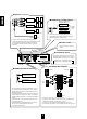
ENGLISH ■ PRE OUT connections ■ CONNECTING SYSTEM CONTROL Power amplifier FRONT PRE OUT SUB WOOFER Sherwood component with DIGI LINK II or III Front speakers REAR CENTER CD player Power amplifier Rear speakers System control cord Tape deck Power amplifier Graphic equalizer Center speaker DIGI-LINK ● Powered subwoofer Connect this jack to the DIGI LINK jack of the external Sherwood component that uses the DIGI LINK II or III remote control system.
Front Panel Controls AUDIO/VIDEO RECEIVER RVD-6090R ENGLISH POWER SWITCH SPEAKER MODE BUTTON SPEAKER SWITCH DYNAMIC RANGE BUTTON/INDICATOR FM MODE BUTTON STANDBY INDICATOR MEMORY/ENTER BUTTON REMOTE SENSOR AUDIO/VIDEO INPUT DIGITAL INPUT INDICATORS SELECTOR BUTTONS MASTER VOLUME DOLBYDIGITAL(AC-3) CONTROL KNOB INDICATOR TONE DIRECT INDICATOR T D A S MASTER VOLUME T0TALLY DISCRETE AMPLIFIER STAGE INPUT SELECTOR REMOTE SENSOR DIGITAL DIRECT ST TUNED AUTO POWER TAPE M PRESET ON/OFF STANDBY OPTIC
ENGLISH DIGI LINK III System Remote Controls You can remotely control not only this receiver but also Sherwood compatible components bearing the DIGI LINK II or III logo. For system remote control operation, first make the DIGI LINK connections. PRESET SCAN BUTTON POWER BUTTON ■ CD PLAYER SECTION DISC(CD changer only)-for disc selection - to begin play. - for pausing play. , - for skipping backward or forward. - to stop play or to clear a program. REPEAT A< >B - to play a specific passage repeatedly.
ENGLISH REMOTE CONTROL OPERATION RANGE AUDIO/VIDEO RECEIVER RVD-6090R T D A S MASTER VOLUME T0TALLY DISCRETE AMPLIFIER STAGE INPUT SELECTOR REMOTE SENSOR DIGITAL DIRECT RDS RT TIMER 12 ST TUNED AUTO VCR12V-CD TAPE 2 M PRESET POWER ON/OFF STANDBY OPTICAL dB kHz MHz COAXIAL EON TP TA PTY SPEAKER Pro Logic 3 Stereo THEATER HALL MEM VIDEO ms SLEEP AUDIO DYNAMIC RANGE CINEMA EQ DIRECT SPEAKER MODE FM MODE MEMO/ENTER BAND ON/ TAPE MONITOR CHANNEL SELECTOR OFF TUNING/PRESET 6 CH DIR
Operations ENGLISH LISTENING TO A PROGRAM SOURCE Before operation 3 POWER Enter the standby mode. ON/OFF Select the desired input source. INPUT SELECTOR POWER P.SCAN 1 2 3 6 7 8 4 5 9 0 REPEAT INTRO DISC CD TUNER VCR 1 CD A<
4 6 ENGLISH When CD, VCR2 or DVD is selected as input source Adjust the (over all) volume. Select the digital or the analog input connected as desired. POWER MASTER VOLUME P.SCAN 1 2 3 6 7 8 4 5 9 0 REPEAT INTRO DISC CD A<
ENGLISH 9 To compensate for edgy or shrill movie sound tracks. 10 CINEMA EQ To mute the sound. POWER P.SCAN 1 2 3 6 7 8 4 5 9 0 REPEAT INTRO DISC CD A<
This receiver incorporates a sophisticated Digital Signal Processor that allows you to create optimum sound quality and sound atmosphere in your personal Home Theater. Surround modes This unit has 5 different surround modes to allow you to enjoy surround sound with various program sources: DOLBY DIGITAL(AC-3), DOLBY PRO LOGIC, THEATER, HALL 1, HALL 2. DOLBY DIGITAL(AC-3) : Allows you to enjoy up to 5.
ENGLISH Speaker placement To obtain the best surround sound effect in your home, place the speakers as follows; Front speakers: Place each front speaker about 1m (40″ ) from the TV set. Center speaker: Place the center speaker either above or below the TV set to assure good visualization of center channel program. Rear speakers: Place the rear speakers approximately 1m above the ear level of a seated listener on the direct left and right of them or slightly behind.
3 Adjusting the settings of front, center ,rear speakers, and subwoofer connected. If the speaker setting is adjusted to “S”, the low range bass sound of the channel(s) is redirected to the subwoofer or the front channels and if the speaker setting is adjusted to “N”, the sound of the channel(s) is redirected to other channels.
ENGLISH Adjusting each channel level 7 Adjust the level of the selected channel as desired. 8 Select the desired channel. POWER CHANNEL LEVEL P.SCAN 1 2 3 6 7 8 4 5 9 0 REPEAT INTRO DISC CD POWER A<
Check the delay time to be adjusted. POWER P.SCAN 1 2 3 6 7 8 4 5 9 0 REPEAT INTRO DISC CD A<
ENGLISH LISTENING TO RADIO BROADCASTS Auto tuning 1 2 Select the tuner. BAND MHz INPUT SELECTOR POWER VIDEO AUDIO 2 3 6 7 8 4 5 9 CD TUNER AUX TAPE MON. INTRO SCAN B DECK SEL A TUNER FREQUENCY 0 REPEAT A or BAND P.SCAN 1 DISC CD B DVD/TV VCR1 VCR2 Each time this button is pressed, the band is changed to FM or AM. Pressing the BAND button without first selecting TUNER, will automatically select the tuner.
4 TUNING/PRESET Repeat the above steps 1 to 3 to memorize other stations. MEMO/ENTER MEMORY BACKUP FUNCTION When using the NUMERIC buttons on the remote control. Examples) For “3” : The following items, set before the receiver is turned off, are memorized. INPUT SELECTOR settings Surround mode settings Preset stations,etc.
ENGLISH RECORDING The analog signals from the 6 CH DIRECT inputs as well as the digital signals from the coaxial or optical digital input can be heard but cannot be recorded. The volume and tone (bass, treble) settings, etc. have no effect on the recording signals. Recording with TAPE MONITOR 1 2 Select the desired input as recording source except for TAPE MONITOR. Start recording on the Tape Deck connected to the TAPE MONITOR input. INPUT SELECTOR POWER P.
4 Start play on the DVD and the CD respectively. The audio signal from the CD and the video signal from the DVD will be dubbed and you can enjoy them on the TV set and from the speakers. Note : Be sure to observe the order of the above steps 1 and 2.
ENGLISH Troubleshooting Guide If a fault occurs, run through the table below before taking your receiver for repair. If the fault persists, attempt to solve it by switching the receiver off and on again. If this fails to resolve the situation, consult your dealer. Under no circumstances should you attempt to repair the receiver yourself. This could void the warranty. POSSIBLE CAUSE REMEDY No power PROBLEM The AC input cord is disconnected. Poor connection at AC wall outlet or the outlet is inactive.
Specifications DIGITAL AUDIO SECTION Sampling frequency ....................................................................................................................................... 32, 44.1, 48 kHz Digital input level Coaxial, 75 Ω ........................................................................................................................................................... 0.5 Vp-p Optical, 660 nm .......................................................................................
O P E R A T I N G I N S T R U C T I O N S RVD-6090R AUDIO/VIDEO RECEIVER 5707-04707-001-0