Shibaura Diesel Engine Operation Manuals E673L S773L N843 N843L N844L N844L-T Supported by Hustler Turf Equipment Company and Excel Industries, Inc.
109821_0508
FOREWORD The IHI Shibaura Machinery Corporation (ISM) industrial diesel engines are a product of ISM's long years of experience, advanced technology. Shibaura takes great pride in the superior durability and operating economy of these engines. In order to get the fullest use and benefit from your industrial engine, it is important that you operate and maintain it correctly. This Manual is designed to help you do this.
FEDERAL and CALIFORNIA EMISSIONS WARRANTY WARRANTY STATEMENT IHI Shibaura Machinery Corporation (ISM) warrants that your 2004 and later non-road diesel engine was designed, built and equipped to conform to applicable U.S.
TABLE OF CONTENTS Safety . . . . . . . . . . . . . . . . . . . . . . . . . . . . . . . . . . . . . . . . . . . . . . . . . . . . .6 Engine external views Engine main parts nomenclature . . . . . . . . . . . . . . . . . . . . . . . . . . . . . . . .6 General information 3.1 Engine data and specifications. . . . . . . . . . . . . . . . . . . . . . . . .7 ISM engine after service . . . . . . . . . . . . . . . . . . . . . . . . . . . . . . . . . . . . . .7 Fuel, lubricant and coolant 5.1 Fuel. . . . . . . .
1. Safety In the caution area, we tell you about something that can damage your engine or equipment. Many times, this damage would not be covered by your warranty, and it could be costly. But the caution will tell you what to do to help avoid the damage. Introduction This Operation Manual contains the information you will need to operate the engine correctly. Check that you have the correct Operation Manual for your engine. Read the book carefully before operating or servicing the engine.
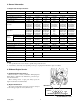
3. General Information 3.1.Engine data and specifications Model Name E673L Engine Type S773L N843 N843L N844L N844L-T Four cycle, water-cooled, in-line overhead valve type Combustion type No.of cylinder-bore×stroke (mm) Swirl chamber 3 - 67×72 3 - 77×81 3 - 84×90 3 - 84×100 4 - 84×100 4 - 84×100 Engine displacement (L) 0.761 1.131 1.496 1.662 2.216 2.216 Compression ratio 23.5 23.5 22.5 22.5 22.5 22.5 * Max output 16.5hp/3000 (12.3kW/3000) 18.5hp/3600 (13.8kW/3600) 24.
5. Fuel, Lubricant & Coolant Number 1-D and Number 2-D). This blended fuel is usually called Number 2-D also, but can be used in colder temperatures than Number 2-D fuel which has not been "winterized". Check with the service station operator to be sure you get the properly blended fuel. Note that diesel fuel may foam during a fill-up. This can cause the automatic pump nozzle to shut off even though your tank is not full. 5.
(1) Engine Oil Selection If fungus or bacteria has caused fuel system problems, you should have your authorized dealer correct these problems. Then, use a diesel fuel biocide to sterilize the fuel system (follow the biocide manufacturer's instructions). Biocides are available from your dealer, service stations, parts stores and other automotive places. See your authorized dealer for advice on using biocides in your area and for recommendations on which biocides you should use.
● 5.3 Coolant Drain oil to the max. oil level if oil level is above the max. level mark. ● Add oil to the max. oil level if oil level is below the min. level mark. 3. Also check the sample oil on the dipstick for fouling and degrees of viscosity. Use 50/50 mix Ethylene Glycol and water for coolant and replace it periodically. (Refer to section 8.2) 6. Engine Operation CAUTION: Oil level check must be made ten or twenty minutes after the engine has been stopped.
1. When the belt is depressed about 5 mm (0.197 in) with the thumb (about 50 N (11 lb) pressure) at midway between the fan pulley and alternator pulley, the belt tension is correct. When the belt tension is too high, it will result in alternator failure. Also, a loose belt will cause belt slippage which may result in damaged belt and abnormal noise. 2. Check the belts. Replace them if any damage is found.
(5) Battery Cable Connection Check the battery cable connections for looseness or corrosion. A loose cable connection will result in hard engine starting or insufficient battery charge. The battery cables must be tightened securely. Never reverse "+" and "-" terminals when reconnecting cables. Even a short period of reverse connection will damage the electrical parts. 6.2 Engine Starting (1) Preparation before starting 1. Make sure that all hydraulic control levers etc.
● The exhaust smoke color after engine warming-up and at no load operation: Colorless or light blue . . . . . .Normal (Perfect combustion) Black color . . . . . . .Abnormal (Imperfect combustion) White color . . . . . . .Abnormal (Imperfect combustion) The type with an indicator light, 10 seconds are required until the indicator light at the instrument panel goes off. 2. Turn the starter key clockwise to the “START” position as soon as the indication lamp goes off.
(2) Coolant Temperature If no steam or engine coolant can be seen or heard, open the engine access cover. If the engine coolant is boiling, wait until it stops before proceeding. Look at the see-through reserve tank. The engine coolant level should be between the "MAX" and "MIN" marks on the reserve tank. If necessary, pour engine coolant into the reserve tank only, never directly into the radiator. Also, do not check engine coolant level at the radiator.
6.8 Starting the Engine After Being Left Unused For A Long Period of Time (5) Abnormal Engine Noise Pay attention to the noise from the engine or other related parts, confirming normal operating noise. When the equipment is left unused for "more than three months" without running the engine, conduct a thorough inspection of the vehicle before starting the engine. After starting the engine, be sure to warm it up for more than ten minutes at idling.
CAUTION: Drain the used engine oil into an approved oil container. Dispose of used oil properly. Pour oil slowly to prevent oil from flowing into the air intake manifold 2 Oil Fill 1 1. 2. 3. 4. 4 Oil filter Oil filler cap Oil sump Drain plug 3 Oil filter element removal Use a filter wrench to remove the cartridge type oil filter. Oil filter Oil Fill N843 & N843L Loosen Tighten Oil filter element installation 1. Apply light coat of engine oil to the O-ring. 2.
7.2 Cooling System When changing the engine oil, add the exact amount specified in the engine owner’s manual. NOTE: Use CD grade or better by API classification engine oil. MODELS N843 & N843L ONLY — Add oil at the oil fill shown. When changing the engine oil, add the exact amount specified in the engine owner’s manual. Use CD grade or better by API classification engine oil. 3. Wait about fifteen minutes until the oil gets down to the oil pan. Then check the oil level with a dipstick.
Loosen Filling with coolant 1. Close or tighten the coolant drain plug. Using a 50/50 mixture of Ethylene Glycol and water (Refer to section 8.2) fill the radiator with the coolant until the level comes up to the filler port neck. 2. Fill gradually to prevent air entry. Coolant volume (Engine only) : Refer to "Main Data Specifications" 3. After filling operate the engine about five minutes at a low idle speed to purge the air from the system. The coolant level will drop.
CAUTION: If the cup is removed without turning the lever as instructed, the fuel may flow out. 2. Loosen the ring nut, remove the cup, and take out the element. 3. Clean the cup, install a new element, and install new packing on the ring nut. 4. Tighten the cup to the body securely with the ring nut. 5. After installation, turn the fuel filter lever to the open position. WARNING: 1. With the fuel lever in the “OFF” position, the engine cannot be started. 2.
Follow the equipment manufacturer's recommendation for intervals. Loose connections will cause hard engine starting or insufficient battery charging. If the terminals are excessively corroded, disconnect the battery cables and polish them with a wire brush or sandpaper. Never reverse the "+" and "-" terminals when reconnecting the cables. Even a short period of reverse connection could damage the electrical system.
Then measure and adjust the clearance of the other valves. Faulty Good Cylinder No. 1 2 Valve arrangement I E I When No.
(5) Starter and Alternator Servicing Service the starter and alternator every 1000 hours of operation. Do the following: 1. Starter commutator cleaning 2. Alternator slip ring cleaning 3. Carbon brushes and the brush contact check components of the cooling system and because of its low boiling point. 2. High silicate antifreeze is not recommended because it could cause serious silica gelation problems. 3. Usage and mixing ratio etc. should be followed to the antifreeze manufacture's recommendations.
9. Engine Maintenance Schedule When performing the following items, the daily inspection items should also be carried out.
Daily Description of check and Maintenance 17 Cooling system circuit cleaning 18 Radiator filler cap function check (*) 19 Electrolyte level check X 20 Battery cleaning X 21 Battery charge condition Initial 50 Every 100 Every 200 Every 400 Every 600 Every 1000 Remarks Yearly Charge warning lamp X See ' EXPLANATION OF MAINTENANCE SHEDULE' NO X 22 Electrolyte gravity check X 23 Starter and alternator check and cleaning(*) X 24 Wiring and connection check X 25 Preheating cond
15. Coolant replacement 16. Radiator external cleaning 17. Cooling system flushing 18. Radiator filling cap function check 19. Electrolyte level check 20. Battery cleaning 21. Battery charge condition 22. Electrolyte gravity check 23. Starter and alternator check and cleaning 24. Wiring and connection check 25. Preheating condition check 26. Air cleaner element replacement 27. Engine starting condition and noise condition 28. Exhaust smoke condition 29. Cylinder compression pressure 30.
Engine does not start. Starter does not turn. Starter turns but engine does not start. Battery discharged. Loose cable connections. Starter or starter switch failure. Safety relay failure. No fuel injection. Engine starts but stalls immediately. Fuel is injected but engine does not start. No fuel in the fuel tank. Clogged fuel filter element or strainer. Air in the fuel system. Feed pump malfunction. Control rack is stuck at no fuel position. Improper preheating operation. Glow plug malfunction.
Unstable engine running Unstable low idling Too high low idling speed. Incorrect control lever adjustment. Crack in injection pipe. Injection nozzle failure. Engine stop lever restricted at stop position. Uneven compression pressure between cylinders. Engine hunting in medium speed range. Incorrect control lever adjustment. Governor internal malfunction. Malfunction in engine at high speed range. Governor spring deteriorated. Insufficient fuel supply. Air in the fuel system.
Low oil pressure Lack of oil Improper oil Oll leakage Large oil consumption. Clogged filter and strainer. High lubricating oil temperature Wrong selection of kind and viscosity. Over heat Worn bearings and oil pump. Faulty relief valve. Lack of power Incorrect injection pump adjustment. Poor cylinder compression pressure. Injection nozzle malfunction, Cylinder compression pressure leakage.
Condition Improper color of engine exhaust (white or blue) Improper engine exhaust (black or dark gray) 109821_0508 Cause Remedy Too much engine oil. Too low viscosity of engine oil. Improper fuel. Improper injection timing. Engine oil burning or detonation. Overload. Clogged air cleaner. Improper fuel. Excessive fuel injection. Improper function of fuel injection pump. Clogged fuel filter. Improper function of engine main body. 29 Check and adjust the quantity. Check and change.
All information, illustrations and specifications contained in this manual are based on the latest product information available at the time of publication. The right is reserved to make changes at any time without notice. OPERATION MANUAL (INDUSTRIAL) E673L S773L N843 N843L N844L N844L-T Issued by IHI Shibaura Machinery Corporation, Ltd.