SLOPE MOWER 0
TO THE OWNER: This manual contains information concerning operation, adjust, and maintenance of the SG280 Mower. You have purchased a dependable machine, but only by proper care and operation you can expect to receive the performance and long service built into this Mower. Please have all operators read this manual carefully and keep the manual available for reference. Your SHIBAURA dealer will instruct you in the general operation of your Mower. (Refer to the "Delivery Report" at the back of this manual.
CONTENTS SECTION 1-SAFETY RULES ·································································3 SECTION 2-GENERAL INFORMATION··············································· 11 SECTION 3-NAME OF EACH PART ···················································· 14 SECTION 4-FUNCTION OF EACH PART ············································ 16 SECTION 5-CHECK BEFORE OPERATION········································ 23 SECTION 6-DRIVING AND WORK ······················································25 SECTION 7
SECTION 1-SAFETY RULES 1. SAFETY RULES 4) Never use the Slope Mower. Please pay particular attention to all boxed parts in the text which have the sign . - When people, especially children, or pets are nearby. This sign warns you to be careful when carrying out certain functions. - If the operator has taken medicine or substances that can affect his ability to react and concentrate. DANGER: Denotes immediate hazards which WILL result in severe personal injury or death.
SAFETY RULES 2) Thoroughly inspect the area where the equipment is to be used and remove all objects which may be thrown by the machine (stones, sticks, metal wire, bones, etc.) 3) WARNING: Engine fuel is highly flammable: 5) Do not operate on slopes of more than 22°(40%) in basic configuration. This machine will operate on more than 22°slopes. This is in conjunction with operator training, correct weight, correct maintenance of the machine and appropriate conditions.
SAFETY RULES - Before checking, cleaning or working on the Slope Mower; - After striking a foreign object. Inspect the Slope Mower for damage and make repairs before restarting and operating the Slope Mower; - If the Slope Mower starts to vibrate abnormally (immediately check and remove the cause of the vibration) 11) Disengage drive to blades when transporting or not in use. Disengage the blades and wait for them to stop before emptying the grasscatcher.
SAFETY RULES 5) Check the deflector and grass-catcher frequently for wear and deterioration. 17) Never perform service underneath machine if it is not completely stable. 6) For reasons of safety, do not use the equipment with worn or damaged parts. Parts are to be replaced and not repaired. Use genuine spare parts. Parts which are not of an equivalent quality can damage the equipment and could be dangerous for your safety. 18) Be careful of Hot Oil Under High pressure.
SAFETY RULES - After the completion of loading, lower the implement. Then, stop the tractor engine and set the parking brake (for tractor). - Fix the tractor vehicle with a strong rope. 2) Unloading on the truck - Please do the unloading work under the opposite procedure of loading 3) Warning - Set the parking brake for truck. - Remove the mud from the tractor tires in order to prevent vehicle from slipping sideways on the ramps.
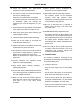
SAFETY AND INSTRUCTION DECALS Your Slope-mower must be used with care. Therefore, decals have been placed on the machine, to remind you pictorially of main precautions to take during use. Their meaning is explained below. We also strongly recommend to carefully read the safety instructions given in the concerned chapter of this manual. • Never touch rotating parts while engine is running. SAFETY DECALS MAX 30° 30° • Stay clear of hot surface. • Read this Operator’s Manual before using the Slope-mower.
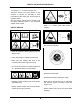
SAFETY AND INSTRUCTION DECALS INSTRUCTION DECALS ② ① • Do not open when hot. • Contents under pressure. ③ Parking Brake ① Parking Brake ② “Lock” Position ③ “Release” Position • Always wear seat belt. Key Switch ① ② ③ ④ • Do not attach ropes or chains to ROPS for pulling purposes. Use of ROPS and seat belt reduce the chance of injury or death if rollover or upset occurs.
SECTION 2-GENERAL INFORMATION MACHINE IDENTIFICATION PLATE ① ② ③ ④ ⑤ ⑥ ⑦ CE Conformity Mark Weight in kgs Name and Address of Manufacturer Type of Front Mower Serial Number Engine Power Engine Number ④ ⑤ ③ ⑦ ⑥ ② 10 ①
GENERAL INFORMATION PLEASE READ CAREFULLY: For a complete list of the pre-delivery service checks performed by your dealer, refer to the PRE-DELIVERY SERVICE checklist found at the back of this manual. Keep one copy as your record of the service performed. The other copy should be removed from the manual and kept by your dealer. MAKE SURE THAT BOTH COPIES ARE COMPLETED AND THAT YOU AND THE DEALER SIGN BOTH COPIES. A PRODUCT IDENTIFICATION PLATE is located in the front frame of the mower.
GENERAL INFORMATION MINIMUM HARDWARE TIGHTENING TORQUES IN FOOT POUNDS (NEWTON-METERS) FOR NORMAL ASSEMBLY APPLICATIONS METRIC HARDWARE AND LOCKNUTS GENERAL INFORMATION 12
INTERNATIONAL SYMBOLS As a guide to the operation of your tractor, various international symbols have been used on instruments and controls. These symbols are depicted and described below.
SECTION 3-NAME OF EACH PART 1. Vehicle Fig. 3-1 Fig.
NAME OF EACH PART 2. Operation System Fig. 3-3 Fig.
SECTION 4-FUNCTION OF EACH PART 1. Steering Wheel and Seat Systems ③ Rolling seat Seat angle can be adjusted when you operate on ① Steering wheel a slopes. Angle of the steering wheel can be adjusted. Position of the steering wheel can be adjusted By grasping the seat swing lever above the oil tank, the seat rolls laterally in 2 steps to 12.5 and by pulling the tilt lever. After the position is determined, pull down the tilt lever forward and fix. Do not adjust these 15°.
FUNCTION OF EACH PART ④ Seat belt (ROPS) DO NOT ATTEMPT BYPASS SEAT SAFETY INTERLOCK SWITCH. Seat Belt ● When driving the vehicle, always fasten the seat belt. ● Fasten the seat belt extending over the hips. If the seat belt is not applied, death or serious injury may be caused in the event of roll over, tumbling, rear end collision or other accidents. ● DO NOT remove a ROPS and seat belts. ROPS when used with seat belts is effective in reducing injuries during unit overturn accidents.
FUNCTION OF EACH PART 2. Engine Control System ② Meters and Pilot Lamp ① Main switch Caution ● While the machine is not in service, be sure to pull out the key and store it in a safe storage place. If not, some accident may be caused. The key is used to start the engine. [HEAT] If you release your hand from the key at the position to preheat the combustion chamber, the key will automatically return to the “OFF” position.
FUNCTION OF EACH PART • Engine oil pressure pilot lamp When the main switch is turned to the “ON” position, the lamp lights up. When the engine starts operation, the lamp goes out. If the lamp lights up while Fig. 4-12 the engine is rotating, there is a fault in the lubrication pressure circuit. Stop the engine immediately and check for the trouble. • Engine rev. counter / elapsed time integrator • Glow lamp While the engine is running, its number of Fig.
FUNCTION OF EACH PART 3. Traveling and Mower Clutch System ③ Parking brake lever ① Gear shift lever Used to park the vehicle. Used to change the traveling speed. Vehicle speed can be selected from “L” (low By pressing the brake pedal fully and pulling up speed) (4 WD) and “H” (high speed) (2 WD). the lever, the parking brake is applied.
FUNCTION OF EACH PART ④ Forward/reverse pedal ⑤ PTO clutch lever Pedal to travel the vehicle. Lever to engage to the mower and rotate the blades. Press forward pedal down to drive the vehicle forward and the reverse pedal to reverse it. No clutch pedal is provided on this machine. Speed is increased or decreased by the By moving the PTO clutch lever to “ON”, the amount the pedal is depressed. blades rotate.
FUNCTION OF EACH PART 4. Hydraulic System ① Mid mower lifting lever Used to lift or lower the mower. By pushing down the lever rearward, the mower rises. When you release your hand from the lever, it automatically returns to the neutral position. By setting the lever to the lowering position, the lever is held at the lowered position and the mower becomes free to float over undulating ground.
SECTION 5-CHECK BEFORE OPERATION Caution Danger ● ● Always stop the engine and apply the heated muffler, engine and other parts have services or adjustment. completely cooled down. If not, you may be While the engine is running or hot, never burnt. ● When removing covers or other components Do not hold a cigarette in your mouth or for inspections or services, always reinstall use a naked flame when supplying fuel. them.
CHECK BEFORE OPERATION 2. Inspection Method Users of this machine should perform start-up inspection before starting operation every day to ensure safe and comfortable operation, according to the procedure below. if any, immediately. Correct extraordinary conditions, If any problems are felt during operation, inspect and repair without delay.
SECTION 6-DRIVING AND WORK 1. Break-in Operation (first 50 hours) 2. Starting and Stopping the Engine Warning Handling of a new vehicle in the initial 50 hours is very important. Break-in operation greatly influences the life and performance of machines. ● When starting the engine, sit down on the Handle the driver’s seat and check the lever position and machine correctly paying attention to the safety of surroundings. If not, injury accidents following points particularly during this period.
DRIVING AND WORK ① Starting the engine ● The starter consumes large current. Never operate it continuously for more than 10 seconds. (If the engine is not started within 10 seconds, turn off the switch, wait for more than 1 minute and then repeat the starting procedure again.) ● Never turn the key switch to the “starting position” while the engine is running. (1) Pull up the bonnet cover. (2) Set the fuel strainer tap to the “O” (open) position. [Reference:] ● This machine is hydraulically operated.
DRIVING AND WORK 4. Starting, Turning and Stopping Method ③ Stopping and Parking Warning ● When starting the vehicle, check for people around the vehicle, confirm safety in the surrounding areas and start the vehicle slowly avoiding an abrupt start. Failure to do this may result in injury or may cause accidents. Warning ● When you leave the vehicle, park it on solid, flat and stable ground.
DRIVING AND WORK ① Caution for mower operation (1) If you operate a mower for the first time or are not familiar with machines, learn how to operate it on a flat place before commencing work. (2) Select a proper method of mowing operation according to the size or shape of the field, and arrangement of trees and other obstacles. (3) Height of grass varies depending on the type. Most grass is mowed to 51 to 76 mm high. Avoid mowing more than 1/3 of grass height to avoid damage of the grass.
DRIVING AND WORK ⑤ Discharge of grass ⑥ Points of issues and solution ● Warning Uneven mowing Uncut turf remains in rows because of wear or deformation of the blade or too low engine ● ● ● Grass clippings are forcefully discharged. speed. Check the blade for length, wear or For safety, keep the discharge outlet cover deformation, or engine speed and operation always in position. speed. Do not direct the discharge outlet to people ● Separation of turf during operation.
DRIVING AND WORK 6. Loading onto and Unloading from Truck Warning ● When loading the vehicle onto or unloading from a truck, stop the truck engine, apply the hand brake to prevent the truck from moving and apply a chock to the vehicles wheel. Park on a flat place where the traffic is safe. ● (1) Raise the implement to a height not to allow the implement to touch the loading ramps. (2) Position the implement straight to the loading ramps and load it slowly.
DRIVING AND WORK 7. Power Steering 8. Front Weight Caution ● Caution While the engine is running, the steering wheel can be operated very lightly. You Optional front weight is available for this should carefully operate the steering machine. When performing works on a steep wheel when driving at a high speed. If slope, install the front weight. not, an accident may be caused. Power steering is active only when the [Front Weight Installing Method] engine is running.
DRIVING AND WORK 9. Towing when self-propelled running is Caution impossible ● If the vehicle becomes unable to be driven because of failure of the hydraulic ● system or for other reason, it is possible than one full rotation. to move the vehicle by opening the ● ● Stop the engine when the vehicle is towed. hydraulic circuit so that the wheels can To start the engine again, tighten the unload rotate and allow the vehicle to move. valve.
SECTION 7-MAINTENANCE AFTER THE WORK 1. Maintenance Services after Operation 2. Opening/closing the bonnet (1) Release the right and left bonnet catches. Danger ● (2) While pushing the left lock pin in the bonnet front with a round rod, raise the bonnet. Before covering the vehicle with a sheet, (Make sure that the bonnet lock is unlocked.) stop the engine and wait for the engine and muffler to cool down completely.
MAINTENANCE AFTER THE WORK 3. Cleaning the Radiator Grass attached to the dashboard or radiator screen may cause overheat. Before starting and after completing operation, always check and clean 警告 the screen and check it during operation depending on the operation conditions. 4. Services when not using for long time Warning ● When storing the vehicle, remove the battery and pull out the key and store it. If not, an accident may be caused.
SECTION 8-INSPECTION AND MAINTENANCE Warning ● Carry out inspections and maintenance services in a flat and stable place where there is no traffic danger or the machine may not fall over or move, applying a car lock. If these precautions are not observed, the machine may fall over or other accident may happen. Caution ● Undergo semiannual inspections and services for the maintenance of each part. Replace the fuel pipe and power steering hose every 2 years.
INSPECTION AND MAINTENANCE 1. Periodical Inspection List ○Inspection Vehicle ●Replacement 600 hours 550 hours 500 hours 450 hours 400 hours 350 hours 300 hours 250 hours 200 hours 150 hours 100 hours Item 50 hours Time on hour meter Referenc e page Inspect every 5 hours after the start of operation.
INSPECTION AND MAINTENANCE 2. Oil, Grease and Antifreeze Liquid Fuel (F) Diesel light oil Engine oil (E.O.) 10W-30 (API class, CC and CD grade) Mower gear oil (G.O.) SAE90 Hydraulic oil (H.O.) Shibaura HST oil (ISO VG46) Antifreeze liquid, Castrol LLC-95 Cooling oil (C) (Mixing ratio of antifreeze liquid at the time of shipment is outside temperature – 30°C Grease (C.G.) All-purpose grease No.2 Fig. 8-1 37 No.
INSPECTION AND MAINTENANCE 4. Fuel Inspection and Oiling 5. Check and Oil Exchange of Each Part Danger Danger ● No smoking or naked flames when ● supplying fuel. ● After replenishing the fuel, tighten the fuel Caution cap firmly and wipe away spilled fuel. ● Do not top up oil while the engine is running or hot. If not, a fire may be caused. • Check the level of remaining fuel in the fuel tank on the level gauge.
INSPECTION AND MAINTENANCE [Caution for Handling] ● Check the oil level before starting the engine or while the engine is cold. ● To check the oil level, place the vehicle on a horizontal place and check while the oil surface is horizontal. ● Never discard waste oil to a river or sewage. Ask a professional to discard the waste oil or take some other appropriate means. Exchange Discharge the oil from the drain plug under the engine.
INSPECTION AND MAINTENANCE 6. Replacing Filters ② Oil Filter ① Engine Oil Filter The oil filter is of the cartridge type. Replace The filter is of the cartridge type. Replace the the oil filter initially after 50 hours and then filter initially after 50 hours and then every 200 every 300 hours. hours of operation. Replacement Replacement (1) After discharging the hydraulic oil, turn the (1) After discharging the engine oil, turn the filter counterclockwise to remove.
INSPECTION AND MAINTENANCE ③ Fuel Filter Cleaning and Replacement (1) Turn the fuel tap to the “C” (closed) position. (2) Remove the filter cup and remove the water and dust in the filter cup. (3) After completion of filter cleaning, install it to the original position and turn the fuel tap to the “O” (opened) position. The fuel feed pump of this machine is driven from the cam shaft. After it is operated for cleaning or replacement, remove the cap and discharge the air in the filter cup.
INSPECTION AND MAINTENANCE 7. Exchanging the Cooling Water (2) Wash inside of the radiator with water until no dust or rust comes out. ※ By supplying water containing radiator Dangerous Do not open the radiator cap while the engine is running or immediately after the engine stops. Open it after the engine stops and has cooled down. If not, hot water may spurt out and you may get burnt. Inspection Open the bonnet and check that the coolant in the reserve tank is between the upper limit and lower limit.
INSPECTION AND MAINTENANCE 8. Cleaning and Replacing the Air Cleaner The air cleaner removes dust contained in supplied air to protect the cylinder and piston ring from wear and keep the engine in good condition for a long time. The air cleaner is composed of outer and inner elements. 9. Inspecting the battery The battery of this vehicle has no vent plug and does not need be replenished with water. (The battery is sealed type without the necessity to replenish water in the overall life.
INSPECTION AND MAINTENANCE 10. Inspection of Pipes Warning ● Danger When connecting the battery, connect the (+) side first and, when disconnecting it, remove the (-) side first. If not, short circuit ● and burn injury may result. Check the fuel pipe, radiator hose, and power steering hose for damage and leakage of fuel, oil or water and check the clamps for looseness. Danger Replace them every 2 years even if not damaged. 11. Inspecting Electric Wires ● Avoid fast pressure charging.
INSPECTION AND MAINTENANCE 13. Inspecting and Adjusting the Fan Beltt Caution ● Be sure to stop the engine. ● Inspect and adjust the fan belt after the engine has completely cooled down. If not, you may get burnt. Fig. 8-17 Front wheel pivot shaft Open the bonnet, push an intermediate point of the fan belt by a force of about 100N (10kgf) and check that the deflection of the belt is about 10 to 15mm and check for damage of the belt.
INSPECTION AND MAINTENANCE 14. Cleaning the Radiator 15. Inspection and Replacement of Fuse and Slow Blow Fuse Caution Remove the cover of the fuse and check the ● Remove dust or grass deposited or entangled on the inside. Remove grass and other dust deposited around the V belt or engine frequently. If not, a fire may be caused. fuse. Stop the engine and check the slow blow fuse. If the fuse blows out, replace with new one of specified capacity. Fig. 8-22 (1) Open the bonnet.
INSPECTION AND MAINTENANCE 16. Inspecting the Tire ① Inspection of Tire Check the tires of the front and rear wheels for proper air pressure. It can be visually checked as illustrated below.. 18. Inspection and Adjustment of Brake Warning ● Check the brake for correct operation. If not, an accident may be caused. Press the brake pedal and check for specified allowance (5 – 10mm) and same functioning on the right and left sides.
INSPECTION AND MAINTENANCE ② Adjustment of belt tension (1) Open the bonnet. (2) Set the mower clutch lever to the “ON” position and adjust the belt tension. Proper belt tension is such that the approximate center is deflected 5mm when pressed by a force of 49N (5kgf). Adjust the tension properly in the procedure below. (3) Loosen the tension wire lock nut and adjust the wire length. (4) After the belt tension is properly adjusted, tighten the lock nut. 19.
SECTION 9-TROUBLE SHOOTING Warning ● Refer to following chart if you find the machine not working correctly. Stop the engine first before start inspection. 1. Engine related condition Condition Check Point Remedy Safety switch may be functioning. Set the PTO lever to “OFF”, release your foot from the traveling pedal, and turn the key switch pressing the brake pedal. Level of battery electrolyte or battery Replenish the battery electrolyte to the discharge specified level and charge the battery fully.
TROUBLE SHOOTING Condition Inspection Point Remedy White smoke emitted Excessive engine oil Discharge excessive oil. from the muffler Too low viscosity of engine oil Change the oil to one of proper viscosity. Decreased engine oil Replenish the oil to specified level. Engine oil lamp lights Too low engine oil viscosity Change the oil to one of proper viscosity. up while driving Failed pressure switch Replace the switch. Failed oil pump Subject to repair by a service dealer.
TROUBLE SHOOTING 4. Electric System Condition Lamp does not light up. Inspection Point Remedy Burnt-out light bulb Replace the light bulb. Blown fuse Replace the fuse. Improper connection of wiring Inspect and connect firmly. Failed switch Replace the switch. Tighten the earth wire firmly to the main Improper earthing body. Discharged battery Charge.
SECTION 10-CONSUMABLE PARTS 1. Main consumable parts Engine system Part code Name Q’ty/unit 08010 9061 Fan belt 1 14051 7020 Engine oil filter 1 36072 0130 Fuel filter 1 Remarks Type A, 36.
SPECIFICATIONS 3. Specifications Vehicle SG280E Overall length Overall width mm Tread Wheel 1580 mm 1200 (handle) /1900 (ROPS) mm 1500 Front wheel mm 1310 Rear wheel mm 1310 Ground clearance Engine 2525 mm Overall height Tread Vehicle body size Model mm Reference clearance 140 (lower side of mower deck) Front wheel size 21×11.00×10 Rear wheel size 21×11.00×10 Model SHIBAURA N843 Type 3 cylinders, water cooled 4 cycle Diesel engine No.
ELECTRICAL DIAGRAM 4.
TIGHTENING TORQUES 5. Tightening Torque List [Hydraulic Hose and Pipe] Tightening hose union nut tightening torque Adaptor (with O-ring) lock nut tightening torque Nominal size G1/4 G3/8 G1/2 Nominal size G1/4 N·m 24.5 49 58.8 N·m kgf·m 2.5 5.0 6.0 kgf·m R screw tightening torque Nominal 1/8 1/4 3/8 1/2 3/4 N·m 21.6 35.3 53.9 84.3 127 kgf·m 2.2 3.6 5.5 8.6 13.0 55 G3/8 G1/2 39.2 49 58.8 4.0 5.0 6.
IHI Shibaura Machinery Corporation TURF CARE EQUIPMENT DIVISION Matsumoto Office: 1-1-1 Ishishiba, Matsumoto-shi, Nagano-ken, 56 390-8714, Japan Telephone: 263-25-4502 Fax: 263-26-7517 SG280E A00810670 0511010 0010 Printed in Japan R