228-90747 Aug. 2009 SPECTROFLUOROMETRIC DETECTOR FOR SHIMADZU HIGH PERFORMANCE LIQUID CHROMATOGRAPH RF-20A/20Axs INSTRUCTION MANUAL Read the instruction manual thoroughly before you use the product. Keep this instruction manual for future reference.
This page is intentionally left blank.
Introduction Introduction Read this manual thoroughly before using the instrument. Thank you for purchasing this instrument. This manual describes the installation, operation, hardware validation, usage cautions, and details on the accessories and options. Read this manual thoroughly before using the instrument and operate the instrument in accordance with the instructions in this manual. Also, keep this manual for future reference.
Introduction Warranty and After-Sales Service Warranty 1. Period: Please consult your Shimadzu representative for information about the period of this warranty. 2. Description: If a product/part failure occurs for reasons attributable to Shimadzu during the warranty period, Shimadzu will repair or replace the product/part free of charge.
Warranty and After-Sales Service 11) Consumable items Note: Recording media such as floppy disks and CD-ROMs are considered consumable items. ∗ If there is a document such as a warranty provided with the product, or there is a separate contract agreed upon that includes warranty conditions, the provisions of those documents shall apply.
Introduction Safety Instructions • To ensure safe operation of the instrument, read these Safety Instructions carefully before use. • Observe all of the WARNINGS and CAUTIONS described in this section. They are extremely important for safety.
Safety Instructions Installation Site Precautions !WARNING • The solvents used in high performance liquid chromatograph are flammable and toxic. The room where the instrument is installed should be well ventilated; otherwise, solvent vapors could cause poisoning or ignite and cause a fire. • High performance liquid chromatograph uses large amounts of flammable organic solvents. Use of open flame in the vicinity of this instrument must be strictly prohibited.
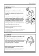
Introduction Installation Precautions To ensure safe operation, contact your Shimadzu representative if product installation, adjustment, or reinstallation (after the product is moved) is required. !WARNING • Take measures to prevent the instrument from falling in the event of an earthquake or other disaster. Strong vibrations could cause the instrument to fall over, resulting in injury. • The power supply voltages and power consumptions of this instrument are listed below.
Safety Instructions !WARNING • Do not place heavy objects on the power cord, and keep any hot items away. The cord could be damaged, resulting in fire, electrical shock or malfunction. If the cord becomes damaged, contact your Shimadzu representative immediately. • Do not modify the cord in any way. Do not bend it excessively or pull on it. The cord could be damaged, resulting in fire, electrical shock or malfunction. If the cord becomes damaged, contact your Shimadzu representative immediately.
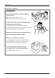
Introduction Operation Precautions !WARNING • Take thorough measures to prevent buildup of static electricity. ^ "Static Electricity Precautions" P.X Static electricity could result in fire or explosion. • Always wear protective gloves and goggles when handling solvents and samples. If solvent gets into the eyes, blindness could result. Should solvent get into the eyes, flush immediately with large amounts of water and get medical attention.
Safety Instructions Precautions for Instrument Inspection, Maintenance, Adjustment and Care !WARNING • Unplug the instrument before inspection, maintenance, or parts replacement. Failure to do so may cause electrical shock or short-circuit accidents to occur. • Never remove the main cover. This may cause injury or malfunction of the instrument. The main cover does not need to be removed for routine maintenance, inspection and adjustment.
Introduction Static Electricity Precautions Liquid chromatograph (LC) uses flammable organic solvent(s) as the mobile phase. LC systems are also often used where large amount of flammable substances are present. Thus, an accident can produce large scale damage. Operators must be constantly on guard against accidents involving fire or explosion. The major cause of these accidents is static electricity.
Static Electricity Precautions Preventing Static Electricity Accidents The best way to prevent static electricity accidents is simply to prevent the occurrence and accumulation of electrostatic charges. !CAUTION • It is important to take multiple preventive measures without fail. • If large amounts of flammable solvents are collected in a large container, implement preventative measures 1, 2, and 3 below. Preventive Measure 1 Use a metal container for waste liquid, and ground the container.
Introduction Preventive Measure 2 Cover the spaces between the tubing and the sides of the inlet and outlet openings of the waste container with caps or other protective covering. This will prevent any sparks generated outside the container from getting inside. Accessories for this measure Caps for 18-L or 4-L container (with three 3-mm diameter openings) Part No. 228-21354-91 Preventive Measure 3 Keep electrostatically charged objects, including the human body, away from the waste liquid container.
Static Electricity Precautions Preventive Measure 5 If it is not possible to use a conductive waste liquid container, take the following precautions: • Ensure that the end of the inflow tubing is always submerged inside the container. Also, place some type of grounded metal object, such as a ground wire connected to the instrument, into the liquid. !CAUTION The above precaution will be ineffective for low conductivity (less than 10−10 S/m) liquids.
Introduction In an Emergency !WARNING If any problem is detected, such as a burning smell, take the following action: Procedure 1 2 Turn the power to the instrument OFF. Disconnect the power cable at the rear of the instrument. When the instrument is used again, inspect the instrument and, if necessary, contact your Shimadzu representative to request servicing. During a Power Outage !CAUTION Take the following measures in the event of a power outage.
Precautions for Mobile Phase Selection and Use Precautions for Mobile Phase Selection and Use !CAUTION • If PEEK resin parts are used in the plumbing, do not use the following mobile phases.
Introduction Precautions for the Xenon Lamp !WARNING • When handling a Xenon lamp, always wear the following protective gear: a protective mask, a thick long-sleeved shirt, and safety gloves. Gas at high pressure is enclosed in the Xenon lamp. If the lamp is subjected to a strong impact or the glass part is damaged, it may explode, scattering fragments. Use a protective mask that is able to cover the entire face with rigid plastic or similar material.
Precautions for the Xenon Lamp !WARNING • Make sure that the Xenon lamp has cooled sufficiently before attempting to replace it. Immediately after being turned OFF the Xenon lamp is extremely hot and could burn you. The time required for the Xenon lamp to cool is at least 90 minutes after the power to the instrument has been turned OFF, or at least 30 minutes after the lamp has been turned OFF by setting [0] (OFF) for [LAMP] in the parameter settings group. ^ "8.4 Inspecting/Replacing the Xenon Lamp" P.
Introduction Precautions on Replacing Fuses !WARNING • Before replacing fuses, turn the power to the instrument OFF and unplug the instrument. • Only use fuses of the correct type and rating for replacement. Failure to heed the above could result in fire, electric shock or short circuits. ^ "8.5 Replacing the Fuse" P.
Disposal Precautions Disposal Precautions When disposing of the instrument and Xenon lamps, contact your Shimadzu representative. If you dispose of them yourself, do so in accordance with the processing standards determined by law, separately from general industrial waste and household garbage. Materials of the Xenon Lamp The raw materials used in the Xenon lamp are shown below.
Introduction Warning Labels For safety operation, warning labels are affixed to where special attention is required. Should any of these labels peel off or be damaged, obtain replacements from Shimadzu Corporation. Front of the Instrument Warning label (Part No. 228-51555) Warning label (Part No. 228-52371) Back of the Instrument Warning label (Part No. 228-51474) Warning label (Part No.
Warning Labels Side of the Instrument Warning label (Part No.
Introduction Action for Environment (WEEE) To all users of Shimadzu equipment in the European Union: Equipment marked with this symbol indicates that it was sold on or after 13th August 2005, which means it should not be disposed of with general household waste. Note that our equipment is for industrial/professional use only. Contact Shimadzu service representative when the equipment has reached the end of WEEE Mark its life. They will advise you regarding the equipment take-back.
Contents Introduction ......................................................................................................................I Warranty and After-Sales Service ..................................................................................II Safety Instructions ........................................................................................................ IV Application Precautions ..............................................................................................
Contents Chapter 2 Parts Identification and Functions 2.1 Front .................................................................................................................2-2 2.2 Behind Front Cover, Top Panel and Left Side .................................................2-3 2.3 Right Side and Base Panel ..............................................................................2-4 2.4 Back .....................................................................................................
Contents 4.2 4.1.8 Setting Sensitivity .......................................................................................... 4-17 4.1.9 Setting the Flow Cell Temperature (RF-20Axs Only) .................................... 4-19 Measuring in the Dual Wavelength Mode ......................................................4-21 4.2.1 Setting the Measurement Mode .................................................................... 4-21 4.2.2 Setting the Measurement Wavelengths ......................
Contents Setting the Flow Cell Temperature [CELL TEMP] (RF-20Axs Only) .......................5-17 Setting the Response [RESPONSE] .......................................................................5-18 Setting the Sensitivity [SENS] .................................................................................5-19 Setting the Gain [GAIN] ...........................................................................................
Contents Calibration Support Group ...................................................................................... 5-35 5.3.2 Showing the VP Function Screen ................................................................. 5-36 5.3.3 Product Information Group ............................................................................ 5-37 Showing the Serial Number [SERIAL NUMBER] .................................................... 5-37 Showing the ROM Version Number [S/W ID] ............
Contents 5.4 Creating Time Programs ................................................................................5-54 5.4.1 List of Commands That Can Be Used in Time Programs ............................. 5-54 5.4.2 Time Program Edit Screen ............................................................................ 5-56 Example of Creation of a Time Program .................................................................5-57 5.5 5.4.3 Setting the Loop Count of the Program [LOOP] .............
Contents 5.8.2 5.9 Wiring ............................................................................................................ 5-82 Using the Spare Flow Cell Unit / Optional Cell ...............................................5-84 Fitting the Flow Cell Unit ......................................................................................... 5-84 Performing Wavelength Calibration ........................................................................
Contents 7.5.5 Checking Wavelength Accuracy ................................................................... 7-11 Objective .................................................................................................................7-11 Check Procedure (for RF-20Axs) ............................................................................7-12 Check Procedure (for RF-20A) ................................................................................7-16 7.5.
Contents Inspecting the Cell .................................................................................................... 8-6 Fitting the Flow Cell Unit ........................................................................................... 8-7 8.2.2 Simple Cleaning of the Cell ............................................................................. 8-8 Simple Cleaning of the Cell .......................................................................................
Contents Chapter 9 Technical Information 9.1 Installation ........................................................................................................9-2 9.1.1 Installation Site ................................................................................................ 9-2 Suitable Sites and Preparation ..................................................................................9-2 Required Installation Space .....................................................................
Contents 9.3.1 Consumable Parts ......................................................................................... 9-42 9.3.2 Replacement Parts ........................................................................................ 9-42 Optical System ........................................................................................................ 9-42 Flow Cell/Plumbing Parts ........................................................................................
Contents This page is intentionally left blank.
1 1 Configuration Contents 1.1 Overview ......................................................................................................... 1-2 1.2 Features .......................................................................................................... 1-3 1.3 Component Parts ............................................................................................ 1-4 1.4 Optional Parts .............................................................................................
1. Configuration 1.1 Overview This instrument is a spectrofluorometric detector for high-performance liquid chromatograph developed for high performance and multi-function capabilities. The RF-20A/20Axs is capable of the following measurements. • Measurement in the single wavelength mode • Measurement in the dual wavelength mode • Measurement in the spectrum scanning mode • Measurement using a time program In the dual wavelength mode, dual wavelength chromatograms can be output using two wavelengths.
1.2 Features 1.2 Features 1 • Excellent Signal-to-Noise Ratio Performance Excellent S/N ratio performance has been achieved through improvement of the optical system and a highorder digital filter. In addition, the basic performance of the RF-20Axs has also been substantially improved by means such as expanding the range of measured wavelengths. • Incorporation of Sophisticated Functions Measurement of two wavelengths simultaneously enables the output of dual wavelength chromatograms.
1. Configuration 1.3 Component Parts This instrument consists of the parts listed below. Check the parts and their quantities after unpacking. Part RF-20A/20Axs body Part No.
1.4 Optional Parts 1.4 Optional Parts 1 Optional Cells Changing the standard cell to the following optional cells enables use as a detector for a variety of applications including semi-micro LC, metal-free LC, FAST LC and so on. Part Flow cell (RF-20A standard flow cell) Flow cell (RF-20Axs standard flow cell) Temperature controlled flow cell for semi-micro LC Flow cell for inert LC RF-20A/20Axs Part No. Remark 228-45856-92 This is the standard cell for the RF-20A.
1. Configuration Photomultiplier for RF-20A Part Name Part No. Remark Photomultiplier R928-08 200-75021 On replacement with a photomultiplier, the measurement wavelength range is extended to 200 - 900 nm. Photomultiplier R3788 200-75031 On replacement with a photomultiplier, the measurement wavelength range is extended to 200 - 750 nm. Photomultiplier for RF-20Axs Part Name Part No.
2 2 Parts Identification and Functions Contents 2.1 Front ................................................................................................................ 2-2 2.2 Behind Front Cover, Top Panel and Left Side ................................................. 2-3 2.3 Right Side and Base Panel ............................................................................. 2-4 2.4 Back .........................................................................................................
2. Parts Identification and Functions 2.1 Front Keypad Used to configure settings and perform operations with the operation keys. Press to show the operation keys. Display panel Comprises the display screen and LED indicators and displays settings and operations. Power switch Front cover Used to switch the power ON/OFF. Press the switch in to turn the power ON. Press it again (the switch will pop out) to turn the power OFF. Open this cover to remove or install the flow cell or to do the tubing work.
2.2 Behind Front Cover, Top Panel and Left Side 2.2 Behind Front Cover, Top Panel and Left Side 2 Flow cell Monitor the mobile phase eluted from the column here. Cell housing screw Tubing clamp Loosened to enable the flow cell to be pulled out. Secures the tubing that is fitted to the flow cell. Cell outlet tube Connected to the tubing that discharges the mobile phase after analysis. Cell inlet tube (with blue tubing) Connect the tubing from the column here.
2. Parts Identification and Functions 2.3 Right Side and Base Panel Shipping screw (painted red) To prevent shock during transportation. Remove before installation. Leakage drain outlet Liquid that leaks out of the instrument is led from this outlet to an LC-20A series module. 2-4 Shipping screw (painted red) To prevent shock during transportation. Remove before installation.
2.4 Back 2.4 Back 2 [REMOTE] connector For connecting to the system controller. Fuse holders Fuses are set in these. Cooling fan Fan for internal cooling. Power cord connector For connecting the power cord. Analog output connector 2 For connecting to external equipment such as a recorder, Chromatopac (integrator), etc. Analog output connector 1 For connecting to external equipment such as a recorder, Chromatopac (integrator), etc.
2. Parts Identification and Functions 2.5 Names and Functions of Displays and Keypad This instrument is controlled with the keys on the keypad. The display allows you to check the instrument's status. Display panel NOTE • The illustration shows the RF-20Axs. • The display panel may become hot when in use. Keypad 2.5.1 Display Panel The display panel consists of a display screen and LED RF-20A 2 1 indicators.
2.5 Names and Functions of Displays and Keypad No. Display or Indicator Function 1 Indicator function Shows the function of the Xenon lamp. Xe: Xenon lamp lit (No display): Xenon lamp not lit 2 EX (excitation wavelength) Shows the excitation wavelength of the currently indicated channel. 3 Indicated channel Shows the currently indicated channel. This is only displayed when measurement is being performed on multiple wavelengths.
2. Parts Identification and Functions 2.5.2 Keypad This instrument is operated, and settings are made, by using the operation keys on its front face. There are the following two types of keys. These are dummy keys. They are not operational. List of Keys That Can Always Be Operated Key run sleep 2-8 Name Function Display key Pressed to show the operation keys and enable their operation. Zero key To adjust the zero position of analog output connectors 1 and 2.
2.5 Names and Functions of Displays and Keypad List of Keys That Can Be Operated on Pressing the Display Key Key - RF-20A/20Axs Name Function Edit key To activate the edit mode of the time program (from the initial screen). Disp key To switch between channel displays when measuring multiple wavelengths. Scan key To start a spectrum scan. Numeric keys To enter numeric values. Enter key To confirm the values entered for each item setting.
2. Parts Identification and Functions This page is intentionally left blank.
3 3 Preparation Contents 3.1 Cautions on Operation .................................................................................... 3-2 3.2 Turning the Power ON/OFF ............................................................................
3. Preparation 3.1 Cautions on Operation Cautions Prior to Operation • When high-sensitivity analysis is required, light the Xenon lamp ahead of time, taking into account the time taken to achieve a stable baseline. The guide for the stabilization time is 1 hour after the Xenon lamp has lit. • Check that there are no liquid leaks at the flow cell and tubing connections. Cautions During Operation • Make sure that the front cover is closed during measurement.
3.2 Turning the Power ON/OFF 3.2 1 Turning the Power ON/OFF Press the power switch to turn the power ON. Press it again to turn the power OFF. Power switch 3 Press in (power ON) Press again (power OFF) Fig. 3.2 2 When the power is turned ON, all the LED indicators and all the dots in the display matrix light up as shown on the right. This instrument executes the following operations ™™™™™™™™™™™™™™™™ ™™™™™™™™™™™™™™™™ automatically. 3 The version number of the control program is displayed. [V∗.
3. Preparation 6 A memory check is executed. RF-20A CHECKING 7 8 V*.** If there is no abnormality, the screen shown to the right is displayed. The initial screen is displayed. RF-20A V*.** CHECK GOOD Initial screen in the single wavelength mode The operation keys will be displayed and become operable. EX200nm Xe EM300nm 1000.00 Initial screen in the dual wavelength mode EX200nm Xe:ch1 EM300nm 1000.00 NOTE When connected to the system controller, press after the instrument has started up.
3.2 Turning the Power ON/OFF Example Error Message Display If an alarm sounds and [NOT PROTECTED] is displayed: This error message is displayed if the parameters and time program that were set last time were erased on startup of the instrument. 1 Press to cancel the alarm. The content of the parameters and time program will be initialized. 2 3 RF-20AXS V*.** NOT PROTECTED Set new parameters and a new time program.
3. Preparation This page is intentionally left blank.
4 4 Basic Operation Contents 4.1 Measuring in the Single Wavelength Mode ..................................................... 4-2 4.2 Measuring in the Dual Wavelength Mode .....................................................
4. Basic Operation 4.1 Measuring in the Single Wavelength Mode This section explains the procedure for measurement in the single wavelength measurement mode, which is the basic measurement mode of this instrument. For details on the "dual wavelength mode" and "spectrum scanning mode", see the following sections. ^ "4.2 Measuring in the Dual Wavelength Mode" P.4-21 "5.5 Measuring in the Spectrum Scanning Mode" P.
4.1 Measuring in the Single Wavelength Mode 4 5 Press repeatedly until [λ MODE] is displayed. Enter MOD E 1 1:Single 2:Dual and press . This sets the measurement mode to single wavelength. 6 Press 4 Initial screen in the single wavelength mode twice. Setting of the measurement mode ends and you are returned to the initial screen. 4.1.2 EX200n m Xe EM30 0nm 1000.00 EX200n m Xe EM30 0nm 1000.00 Setting the Measurement Wavelengths Set the excitation wavelength and emission wavelength.
4. Basic Operation 3 Press . [ch1] will be displayed. In the initial status, the excitation wavelength can be entered. 4 ch1 EX3 50 EM450 Input 0,2 0 0-900 Enter the excitation wavelength with the numeric keys, then press . This sets the excitation wavelength. 5 Press . The status in which the emission wavelength can be entered will be established. 6 ch1 EX4 00 EM450 Input 0,2 0 0-900 Enter the emission wavelength with the numeric keys, then press . This sets the emission wavelength.
4.1 Measuring in the Single Wavelength Mode 4.1.3 Setting the Analog Output Connectors Set whether to connect the Chromatopac (integrator) or recorder to the analog output connectors. When connecting a Chromatopac to an analog output connector set [0], and when connecting a recorder set [1]. The settings for analog output connectors are shown below. They are common to analog output connectors 1 and 2. Set Value Setting 0 ch1: INTEGRATOR Connect a Chromatopac or variable range recorder.
4. Basic Operation 4 Press repeatedly until [ANALOG1 Analog output connector 1 (RF-20A) MODE] or [ANALOG2 MODE] is displayed. ∗ When setting analog output connector 1, display [ANALOG1 MODE] and when setting analog ANALOG1 MODE Input 0 - 1 0 output connector 2, display [ANALOG2 MODE].
4.1 Measuring in the Single Wavelength Mode 6 Press twice. Analog output connector output mode setting ends and you are returned to the initial screen. NOTE To set the output mode of analog output connector 2 right after having set that of analog output connector 1, display the screen on which the output mode of analog output connector 2 can be set by pressing pressing 4.1.4 after in step 5.
4. Basic Operation Details of Output Range Settings These details are common to analog output connectors 1 and 2. Set Value * Output Range 0 Short (output is 0 mV) * 1 ×1 2 × 1/2 3 × 1/4 4 × 1/8 5 × 1/16 6 × 1/32 7 × 1/64 8 × 1/128 9 × 1/256 When a baseline offset value, [BL OFS ANA1] or [BL OFS ANA2], is set, the corresponding set voltage is output.
4.1 Measuring in the Single Wavelength Mode 2 3 4 Press . [PARAMETER] will be displayed. Press PARAMETER Enter to Select . [ch1] will be displayed. Press repeatedly until [ANA1 REC ch1 EX350 EM450 Input 0,200-900 4 Analog output connector 1 RANGE] or [ANA2 REC RANGE] is displayed. ∗ When setting analog output connector 1, display [ANA1 REC RANGE] and when setting analog ANA1 REC RANGE 1 Input 0 - 9 output connector 2, display [ANA2 REC RANGE].
4. Basic Operation 6 Press twice. Setting of the output range for the analog output connector ends and you are returned to the initial screen. ∗ To set the output range of analog output connector 2 right after having set that of analog output connector 1, display the screen on which the output range of analog output connector 2 can be set by pressing after pressing in step 5.
4.1 Measuring in the Single Wavelength Mode 4.1.5 Setting Baseline Offset Values Set baseline offset values for analog output connectors 1 and 2. Connect the recorder or Chromatopac to the analog output connector and set the output range, gain, and sensitivity. ^ "4.1.3 Setting the Analog Output Connectors" P.4-5 "4.1.4 Setting the Output Ranges" P.4-7 "4.1.7 Setting Gain" P.4-16 "4.1.8 Setting Sensitivity" P.
4. Basic Operation Setting the Baseline Offset Values of Analog Output Connectors 1 2 3 4 Press . The initial screen will be displayed. Press PARAMETER Enter to Select . [ch1] will be displayed. Press EM30 0nm 1000.00 . [PARAMETER] will be displayed. Press EX200n m Xe repeatedly until [BL OFS ANA1] or ch1 EX350 EM450 Input 0,200-900 Analog output connector 1 [BL OFS ANA2] is displayed.
4.1 Measuring in the Single Wavelength Mode 5 Enter the offset value (units: mV) from the numeric keys and press . This will change the baseline offset value. 6 Press twice. Setting of baseline offset values for analog output connectors ends and you are returned to the initial screen. After completion of setting, each time you press the baseline returns to the position set 4 here.
4. Basic Operation 4.1.6 Setting the Response (Response Speed) This instrument achieves an improved S/N ratio by using a digital filter. Decreasing the response value of this digital filter improves the responsiveness, but noise is increased. Increasing the response value causes deterioration in responsiveness, but noise is reduced. The response for this instrument can be set at 11 levels, from [0] to [10].
4.1 Measuring in the Single Wavelength Mode 3 4 5 Press . [ch1] will be displayed. Press ch1 EX350 EM450 Input 0,200-900 repeatedly until [RESPONSE] is displayed. RESPON S E Input 0 - 1 0 5 4 Enter the set value from the numeric keys and press . This sets the response. 6 Press twice. Response setting ends and you are returned to the initial screen.
4. Basic Operation 4.1.7 Setting Gain This is the procedure for setting gain. By combining the setting of sensitivity and gain, you can set the measuring range. The settings for gain are shown below. Set Value Gain 1 ×1 2 ×4 3 × 16 The combinations of sensitivity and gain are shown below. Sensitivity Gain 3 (LOW) 2 (MED) 1 (HI) Sensitivity Magnifications 1 Approx. × 1 2 Approx. × 4 3 Approx. × 16 1 Approx. × 32 2 Approx. × 128 3 Approx. × 512 1 Approx. × 1024 2 Approx.
4.1 Measuring in the Single Wavelength Mode 3 4 5 Press . [ch1] will be displayed. Press ch1 EX350 EM450 Input 0,200-900 repeatedly until [GAIN] is displayed. GAIN 2 1:x1 2:x 4 3: x16 4 Enter the set value from the numeric keys and press . This sets the gain. 6 Press twice. Gain setting ends and you are returned to the initial screen. 4.1.8 Setting Sensitivity This is the procedure for setting sensitivity.
4. Basic Operation The settings for sensitivity are shown below. On shipping from the factory, the setting is [2] (MED). Set Value 1 2 3 4 5 Sensitivity Sensitivity Magnifications 1 HIGH Approx. × 1 2 MED Approx. × 32 3 LOW Approx. × 1024 Press . The initial screen will be displayed. Press EM30 0nm 1000.00 . [PARAMETER] will be displayed. Press EX200n m Xe PARAMETER Enter to Select . [ch1] will be displayed.
4.1 Measuring in the Single Wavelength Mode 4.1.9 Setting the Flow Cell Temperature (RF-20Axs Only) Set the temperature of the flow cell. The fluorescent intensity of the sample varies depending on its temperature. In order to obtain stable analysis results unaffected by the ambient temperature, the temperature of the sample in the flow cell is fixed at all times. NOTE The guide for the set temperature of the flow cell is the same temperature as the instrument's ambient temperature.
4. Basic Operation 3 4 5 Press . [ch1] will be displayed. Press ch1 EX350 EM450 Input 0,200-900 repeatedly until [CELL TEMP] is displayed. CELL TEMP 0 0:OFF, 4 - 40°C Enter the set value from the numeric keys and press . This sets the temperature of the flow cell. 6 Press twice. Flow cell temperature setting ends and you are returned to the initial screen.
4.2 Measuring in the Dual Wavelength Mode 4.2 Measuring in the Dual Wavelength Mode This section explains the procedure for measurement in the dual wavelength mode. In the dual wavelength mode you can set the excitation wavelength and emission wavelength of channel 1 and channel 2, and record chromatograms for each channel at the same time. NOTE • When quantifying in the dual wavelength mode, create the calibration curve in the dual wavelength mode.
4. Basic Operation 4 5 Press repeatedly until [λ MODE] is displayed. Enter MOD E 1 1:Single 2:Dual and press . This sets the measurement mode to dual wavelength. 6 Press Initial screen in the dual wavelength mode twice. Setting of the measurement mode ends and you are returned to the initial screen. EX200nm Xe:ch1 EM300nm 10 00.00 NOTE On pressing on the keypad, the indication changes between channel 1 and channel 2. 4.2.
4.2 Measuring in the Dual Wavelength Mode 2 3 Press . [PARAMETER] will be displayed. Press . [ch1] will be displayed. In the initial status, the excitation wavelength can be entered. 4 PARAMETER Enter to Select ch1 EX3 50 EM450 Input 2 0 0-900 4 Enter the excitation wavelength with the numeric keys, then press . This sets the excitation wavelength for channel 1. 5 Press . The status in which the emission wavelength of channel 1 can be entered will be established.
4. Basic Operation 10 Enter the emission wavelength with the numeric keys, then press . This sets the emission wavelength. 11 Press twice. Setting of the excitation wavelength and emission wavelength ends and you are returned to the initial screen. NOTE This instrument has two analog output connectors: analog output connector 1 and analog output connector 2. Set the analog output connector according to the equipment you are connecting to. ^ "4.2.3 Setting the Analog Output Connectors" P.
4.2 Measuring in the Dual Wavelength Mode 4.2.3 Setting the Analog Output Connectors Set whether to connect the Chromatopac (integrator) or recorder to the analog output connectors. In the dual wavelength mode, chromatograms can be recorded simultaneously for channel 1 and channel 2. Here we will set which of analog output connectors 1 and 2 the data of channels 1 and 2 is output to, and whether this data is recorded by a Chromatopac or a recorder.
4. Basic Operation 1 2 3 4 Press . The initial screen will be displayed. Press PARAMETER Enter to Select . [ch1] will be displayed. Press EM300nm 10 00.00 . [PARAMETER] will be displayed. Press EX200nm Xe:ch1 repeatedly until [ANALOG1 ch1 EX350 EM450 Input 0,200-900 Analog output connector 1 (RF-20A) MODE] or [ANALOG2 MODE] is displayed.
4.2 Measuring in the Dual Wavelength Mode Analog output connector 1 (RF-20Axs) ANALOG1 MODE 0 Input 0 - 3,8 Analog output connector 2 (RF-20Axs) ANALOG2 MODE 0 Input 0 - 3,8 5 4 Enter the set value from the numeric keys and press . This sets the output mode of the analog output connectors. ∗ Note that [8] is only displayed on the display panel of the RF-20Axs. 6 Press twice. Analog output connector output mode setting ends and you are returned to the initial screen.
4. Basic Operation 4.2.4 Setting the Output Ranges Before setting the output ranges, set analog output connectors 1 and 2 in accordance with the equipment they will be connected to. ^ "4.2.3 Setting the Analog Output Connectors" P.4-25 NOTE Note that the output range settings only take effect if the analog output connector has been set for RECORDER. ^ "4.2.3 Setting the Analog Output Connectors" P.
4.2 Measuring in the Dual Wavelength Mode Details of Output Range Settings These details are common to analog output connectors 1 and 2. Set Value * Output Range 0 Short (output is 0 mV) * 1 ×1 2 × 1/2 3 × 1/4 4 × 1/8 5 × 1/16 6 × 1/32 7 × 1/64 8 × 1/128 9 × 1/256 4 When a baseline offset value, [BL OFS ANA1] or [BL OFS ANA2], is set, the corresponding set voltage is output.
4. Basic Operation 2 3 4 Press . [PARAMETER] will be displayed. Press PARAMETER Enter to Select . [ch1] will be displayed. Press ch1 EX350 EM450 Input 0,200-900 repeatedly until [ANA1 REC Analog output connector 1 RANGE] or [ANA2 REC RANGE] is displayed. ∗ When setting analog output connector 1, display [ANA1 REC RANGE] and when setting analog ANA1 REC RANGE 1 Input 0 - 9 output connector 2, display [ANA2 REC RANGE].
4.2 Measuring in the Dual Wavelength Mode 4.2.5 Setting Baseline Offset Values Set baseline offset values for analog output connectors 1 and 2. Connect the recorder or Chromatopac to the analog output connector and set the output range, gain, and sensitivity. ^ "4.2.3 Setting the Analog Output Connectors" P.4-25 "4.2.4 Setting the Output Ranges" P.4-28 "4.2.7 Setting Gain" P.4-36 "4.2.8 Setting Sensitivity" P.
4. Basic Operation Setting the Baseline Offset Values of Analog Output Connectors 1 2 3 4 Press . The initial screen will be displayed. Press EM3 00nm 1000.00 . [PARAMETER] will be displayed. Press EX200n m X e:c h 1 PARAMETER Enter to Select . [ch1] will be displayed. Press ch1 EX350 EM450 Input 0,200-900 repeatedly until [BL OFS ANA1] or When setting analog output connector 1: [BL OFS ANA2] is displayed.
4.2 Measuring in the Dual Wavelength Mode 6 Press twice. Setting of baseline offset values for analog output connectors ends and you are returned to the initial screen. After completion of setting, each time you press the baseline returns to the position set here.
4. Basic Operation 1 2 3 4 5 Press . The initial screen will be displayed. Press EM3 00nm 1000.00 . [PARAMETER] will be displayed. Press EX200n m X e:c h 1 PARAMETER Enter to Select . [ch1] will be displayed. Press ch1 EX350 EM450 Input 0,200-900 repeatedly until [RESPONSE] is displayed. RESPON S E Input 0 - 1 0 5 Enter the set value from the numeric keys and press . This sets the response. 6 Press twice. Response setting ends and you are returned to the initial screen.
4.2 Measuring in the Dual Wavelength Mode NOTE If a slow response value (time constant) is set, height is decreased, but the smaller the width at halfheight, the larger is the extent of the decrease in the peak height. Here, as a guide, the situation where a width at halfheight that decreases the peak height by 10 % can be used has been shown for each response.
4. Basic Operation 4.2.7 Setting Gain This is the procedure for setting gain. By combining the setting of sensitivity and gain, you can set the measuring range. The settings for gain are shown below. Set Value Gain 1 ×1 2 ×4 3 × 16 The combinations of sensitivity and gain are shown below. Sensitivity Gain 3 (LOW) 2 (MED) 1 (HI) Sensitivity Magnifications 1 Approx. × 1 2 Approx. × 4 3 Approx. × 16 1 Approx. × 32 2 Approx. × 128 3 Approx. × 512 1 Approx. × 1024 2 Approx.
4.2 Measuring in the Dual Wavelength Mode 3 4 5 Press . [ch1] will be displayed. Press ch1 EX350 EM450 Input 0,200-900 repeatedly until [GAIN] is displayed. GAIN 2 1:x1 2:x 4 3: x16 4 Enter the set value from the numeric keys and press . This sets the gain. 6 Press twice. Gain setting ends and you are returned to the initial screen.
4. Basic Operation 4.2.8 Setting Sensitivity This is the procedure for setting sensitivity. By combining the setting of sensitivity and gain, you can set the measuring range. ^ "4.2.7 Setting Gain" P.4-36 NOTE When using a Chromatopac, select the sensitivity of this instrument such that the noise becomes several percent of the plot range when the [ATTEN] setting of the Chromatopac is [0]. Next, select an [ATTEN] setting that ensures that the targeted peak is within the plot range.
4.2 Measuring in the Dual Wavelength Mode 4 5 Press repeatedly until [SENS] is displayed. SENS 2 1:HI 2:M ED 3:LOW Enter the set value from the numeric keys and press . This sets the sensitivity. 6 Press 4 twice. Sensitivity setting ends and you are returned to the initial screen.
4. Basic Operation 4.2.9 Setting the Flow Cell Temperature (RF-20Axs Only) Set the temperature of the flow cell. The fluorescent intensity of the sample varies depending on its temperature. In order to obtain stable analysis results unaffected by the ambient temperature, the temperature of the sample in the flow cell is fixed at all times. NOTE The guide for the set temperature of the flow cell is the same temperature as the instrument's ambient temperature.
4.2 Measuring in the Dual Wavelength Mode 3 4 5 Press . [ch1] will be displayed. Press ch1 EX350 EM450 Input 0,200-900 repeatedly until [CELL TEMP] is displayed. CELL TEMP 0 0:OFF, 4 - 40°C 4 Enter the set value from the numeric keys and press . This sets the temperature of the flow cell. 6 Press twice. Flow cell temperature setting ends and you are returned to the initial screen.
4. Basic Operation This page is intentionally left blank.
5 5 Application Operation Contents 5.1 Types of Screen and Their Explanations ........................................................ 5-2 5.2 Setting the Auxiliary Functions ...................................................................... 5-12 5.3 Setting the VP Functions ............................................................................... 5-34 5.4 Creating Time Programs ............................................................................... 5-54 5.
5. Application Operation 5.1 Types of Screen and Their Explanations 5.1.1 Types of Screen On turning the power ON, the initial screen appears. Pressing , and on the initial screen displays the following three screens. • Auxiliary function screen • VP function screen • Time program edit screen Auxiliary function screen ^ P.5-3 Initial screen EX200nm Xe EM300nm 1000.00 Press PARAMETER Enter to Select Used to set the auxiliary functions.
5.1 Types of Screen and Their Explanations 5.1.2 Auxiliary Function Screen In this section the auxiliary function screens are shown in the following flow diagrams. On each screen, press to display the next screen, and On auxiliary function group screens, press Press to return to the previous screen. to enter each group. to return to the initial screen. Initial screen EX200nm Xe EM300nm 1000.
5. Application Operation Sensitivity setting ^ P.5-19 SENS 1:H1 2:MED 2 3:LOW Gain setting ^ P.5-19 GAIN 1:x1 1 2:x4 3:x16 Analog output connector 1 output mode setting ^ P.5-20 ANALOG1 Input 0 MODE - 1 0 Analog output connector 2 output mode setting ^ P.5-21 ANALOG2 Input 0 MODE - 1 0 Analog output connector 1 output range setting ^ P.5-22 ANA1 REC RANGE Input 0 - 9 1 Analog output connector 2 output range setting ^ P.
5.1 Types of Screen and Their Explanations EVENT output terminal setting ^ P.5-25 EVENT 0,1,2 0 or 12 Recorder marking setting ^ P.5-25 MARK SETTING Input 0 - 3 Control settings group CONTROL Enter to Press to return to initial screen Select 0 Spectrum scan file specification ^ P.5-26 SCAN 0:BG FILE 1:S1 0 5 2:S2 Scan type setting ^ P.5-26 SPC TYPE 1:EX 2:EM 1 Start wavelength and end wavelength setting for the excitation side (only when [SPC TYPE] is [1]) ^ P.
5. Application Operation Scan speed setting ^ P.5-28 SCAN SPEED Input 1 - 4 2 Plot speed setting ^ P.5-28 PLOT SPD 1 1:1 2:5 3:10nm/s Spectrum output ^ P.5-28 SPC PLOT Enter to System settings group SYSTEM Enter to Press to return to initial screen Select Plot Local mode setting ^ P.5-29 LOCAL 0:Remote 0 1:Local Remote control address setting ^ P.5-29 LINK ADRS Input 1 - 3 12 Key input prohibition ^ P.5-29 KEY CLOSE Enter to Close Brightness setting of display screen ^ P.
5.1 Types of Screen and Their Explanations Program elapsed time indication ^ P.5-31 MONIT-TIME 0:Off 1:On 0 Buzzer sound setting ^ P.5-31 BEEP MODE Input 0 - 0 2 Cell number setting ^ P.5-31 CELL No. Input 1 - 1 10 5 Monitor display group MONITOR Enter to Press Select to return to initial screen Sample side and reference side light intensity indication ^ P.5-32 SMPL REF EN EN 1000 1000 Xenon lamp cumulative operating time indication ^ P.5-32 Xe TIME 0.
5. Application Operation 5.1.3 VP Function Screen In this section the VP function screens are shown in the following flow diagrams. There are four types of VP function: the production information group, the maintenance information group, the validation support group and the calibration support group. Press on the initial screen to show each group screen in succession. Press to return from any group screen to the initial screen.
5.1 Types of Screen and Their Explanations Maintenance log display ^ P.5-39 MAINTENANCE LOG Enter to Display ∗ Press to display and confirm sequentially (up to 20 batches). Operation log display ^ P.5-39 OPERATION LOG Enter to Display ∗ Press to display and confirm sequentially (up to 10 batches). Error log display ^ P.5-40 ERROR Enter or ∗ Press to display and confirm sequentially (up to 10 batches).
5. Application Operation Calibration support group CALIB R A T I O N Press f u n c o r Password entry ^ P.5-43 VP INPUT ***** ∗ If the password PASSWORD doesn't match you cannot proceed to the setting screens. Execution of wavelength calibration ^ P.5-44 ∗ Press WAVE CALIB Enter to Calib to (start) display and confirm. Xenon lamp replacement alert time entry ^ P.5-44 Xe TIME Input Alert 2000 Lv Leak sensor calibration ^ P.
5.1 Types of Screen and Their Explanations Password change ^ P.5-47 CHANGE PASSWORD Enter to Change CBM parameter setting ^ P.
5. Application Operation 5.2 Setting the Auxiliary Functions The auxiliary functions are functions for setting the parameters for measurement and for displaying the settings made. There are the following four types of auxiliary function. Group Main Function PARAMETER To make settings relating to measurement, including wavelength, gain, sensitivity and so on. CONTROL To specify the files in which scan data is saved, set the scan speed, and so on.
5.2 Setting the Auxiliary Functions 5.2.1 List of Auxiliary Functions The auxiliary functions are listed in the tables below. ^ "5.1.2 Auxiliary Function Screen" P.5-3 Parameter Settings Group Name Operation Function Page ch1 Numeric keys To set the excitation wavelength and emission wavelength for channel 1. P.5-16 ch2 Numeric keys To set the excitation wavelength and emission wavelength for channel 2. P.5-16 λ MODE Numeric keys To set the measurement mode. P.
5. Application Operation System Settings Group Name Operation Function Page LOCAL Numeric keys To set whether this instrument is controlled from a system controller or controlled at the instrument itself. P.5-29 LINK ADRS Numeric keys To set the address if the instrument is controlled from the system controller. P.5-29 To block receipt of inputs from the operation keys. P.5-29 KEY CLOSE key BRIGHTNESS Numeric keys To set the brightness of the display panel. P.
5.2 Setting the Auxiliary Functions 5.2.2 1 2 Showing the Auxiliary Function Screen Press . The initial screen will be displayed. Press EX200nm Xe EM300nm 1000.00 repeatedly. The auxiliary function groups will be displayed in the following sequence: [PARAMETER] → [CONTROL] → [SYSTEM] → [MONITOR]. CONTROL Enter to Select 5 3 Select the auxiliary function group to be set and press . This displays the first item within that auxiliary function group.
5. Application Operation 5.2.3 Parameter Settings Group This is the group that relates to parameter settings. PARAMETER Enter to Select Setting the Wavelength for Channel 1 [ch1] Set the excitation wavelength and emission wavelength for channel 1. ^ "4.1.2 Setting the Measurement Wavelengths" P.4-3 ch1 EX350 EM450 Input 0,200-900 "4.2.2 Setting the Measurement Wavelengths" P.4-22 Enter each wavelength with the numeric keys, then press .
5.2 Setting the Auxiliary Functions Setting the Measurement Mode [λ MODE] Set the measurement mode as single wavelength mode or dual wavelength mode ^ "4.1 Measuring in the Single Wavelength Mode" P.4-2 MOD E 1 1:Single 2:Dual "4.2 Measuring in the Dual Wavelength Mode" P.4-21 Enter the measurement mode with the numeric keys, then press . Set Value Measurement Mode 1 Single wavelength mode 2 Dual wavelength mode 5 Setting the Lamp ON/OFF Status [LAMP] Set the ON/OFF status of the lamp.
5. Application Operation Setting the Response [RESPONSE] Set the response. ^ "4.1.6 Setting the Response (Response Speed)" P.4-14 "4.2.6 Setting the Response (Response Speed)" RESPONSE Input 0 - 10 5 P.4-33 Enter the set value from the numeric keys and press . The correspondence between the response values of this instrument and the time constants of an analog CR filter is indicated below. Set Value 5-18 Time Constant (Units: sec) 0 No filter 1 0.05 2 0.1 3 0.5 4 1.0 5 1.5 6 3.0 7 6.
5.2 Setting the Auxiliary Functions Setting the Sensitivity [SENS] Set the sensitivity of the instrument. ^ "4.1.8 Setting Sensitivity" P.4-17 "4.2.8 Setting Sensitivity" P.4-38 Enter the set value from the numeric keys and press SENS 2 1:HI 2:MED 3:LOW . Set Value Sensitivity Sensitivity Magnifications 1 HI Approx. × 1 2 MED Approx. × 32 3 LOW Approx. × 1024 Setting the Gain [GAIN] 5 Set a magnification of the sensitivity (SENS).
5. Application Operation Setting the Output Mode for Analog Output Connector 1 [ANALOG1 MODE] RF-20A Set whether a Chromatopac or a recorder is connected to analog output connector 1. ^ "4.1.3 Setting the Analog Output Connectors" P.4-5 ANALOG1 MODE Input 0 - 1 0 "4.2.3 Setting the Analog Output Connectors" P.4-25 RF-20Axs Enter the set value from the numeric keys and press .
5.2 Setting the Auxiliary Functions Setting the Output Mode for Analog Output Connector 2 [ANALOG2 MODE] RF-20A Set whether a Chromatopac or a recorder is connected to analog output connector 2. ^ "4.1.3 Setting the Analog Output Connectors" P.4-5 ANALOG2 MODE Input 0 - 1 0 "4.2.3 Setting the Analog Output Connectors" P.4-25 RF-20Axs Enter the set value from the numeric keys and press .
5. Application Operation Setting the Output Range for Analog Output Connector 1 [ANA1 REC RANGE] Set the output range for analog output connector 1. Before making this setting, set the output mode of analog output connector 1 to RECORDER. If it is set to INTEGRATOR, this setting will not take effect. ANA1 REC RANG Input 0 - 9 1 ^ "4.1.4 Setting the Output Ranges" P.4-7 "Setting the Output Mode for Analog Output Connector 1 [ANALOG1 MODE]" P.5-20 Enter the set value from the numeric keys and press .
5.2 Setting the Auxiliary Functions Setting the Output Range for Analog Output Connector 2 [ANA2 REC RANGE] Set the output range for analog output connector 2. Before making this setting, set the output mode of analog output connector 2 to RECORDER. If it is set to INTEGRATOR, this setting will not take effect. ANA2 REC RANG Input 0 - 9 1 ^ "4.1.4 Setting the Output Ranges" P.4-7 "Setting the Output Mode for Analog Output Connector 2 [ANALOG2 MODE]" P.
5. Application Operation Setting the Baseline Offset Value for Analog Output Connector 1 [BL OFS ANA1] Set the baseline offset value for analog output connector 1. Before making this setting, set the output mode and output range for analog output connector 1 and connect the recorder or Chromatopac to analog output connector BL OFS ANA1 0 Input -2 - 250mV 1. ^ "4.1.5 Setting Baseline Offset Values" P.4-11 "Setting the Output Mode for Analog Output Connector 1 [ANALOG1 MODE]" P.
5.2 Setting the Auxiliary Functions Setting the EVENT Output Terminal [EVENT] Set the operation of the EVENT output terminal. ^ "5.8 Connection to External Input/Output Terminals" P.5-81 Enter the set value from the numeric keys and press EVENT 0,1,2 or 12 0 . Set Value EVENT1 EVENT2 0 OFF OFF 1 ON OFF 2 OFF ON 12 ON ON Setting Recorder Marking [MARK SETTING] 5 Set marking to be output to a recorder. Enter the set value from the numeric keys and press .
5. Application Operation 5.2.4 Control Settings Group This is the group that relates to control of this instrument. CONTROL Enter to Select Setting the File Number of the File Where the Scan File Is to Be Saved [SCAN FILE] Up to three sets of data generated by spectrum scannings can be saved. Enter the file number with the numeric keys, then press .
5.2 Setting the Auxiliary Functions Setting the Start and End Emission Wavelengths [EM SCAN] Set the start and end emission wavelengths in spectrum scanning. Make this setting when [2] (emission scanning) is set for "Setting the Scan Type [SPC TYPE]" P.5-26. EM SCAN 200-900 Input 200 - 900 Enter the set value from the numeric keys and press .
5. Application Operation Setting the Scan Speed [SCAN SPEED] Set the scan speed for spectrum scanning. Enter the set value from the numeric keys and press . Set Value Scan Speed 1 SUPER (3000 nm/minute) 2 FAST (600 nm/minute) 3 MEDIUM (120 nm/minute) 4 SLOW (24 nm/minute) SCAN SPEED Input 1 - 4 2 Setting the Speed at Which Spectrum Data Is Output [PLOT SPD] Set the speed at which the spectrum data obtained in spectrum scanning is output.
5.2 Setting the Auxiliary Functions 5.2.5 System Settings Group This is the group that relates to system settings, such as connections with external devices. SYSTEM Enter to Select Setting the Local Mode [LOCAL] Set, when the instrument is connected to a system controller, whether it is controlled from that system controller or operated from the unit itself (local mode). Enter the set value from the numeric keys and press LOCAL 0 0:Remote 1:Local 5 .
5. Application Operation Adjusting the Brightness of the Display Screen [BRIGHTNESS] Adjust the contrast of the display screen in four stages. Enter the set value from the numeric keys and press . Set Value Brightness Level (Units: %) 1 25 2 50 3 75 4 100 BRIGHTNESS Input 1 - 4 3 Setting the Function of the EVENT Output Terminal [EXT-S] Set the control mode for external devices according to the EVENT output terminal (EVENT1, EVENT2). Enter the set value from the numeric keys and press .
5.2 Setting the Auxiliary Functions Displaying the Program Elapsed Time [MONIT-TIME] Set whether to display the time elapsed since the start during execution of the time program. Enter the set value from the numeric keys and press . Set Value MONIT-TIME 0:Off 1:On 0 Function 0 The time program elapsed time is not displayed. 1 The time program elapsed time is displayed. When [1] is set, the screen shown to the right is displayed during execution of the time program. EX200nm EM300nm PROG TIME 0.
5. Application Operation Upon entering the cell number set for this instrument, the instrument operates based on the wavelength calibration data that corresponds to the set cell. Enter the set value from the numeric keys and press . Setting Range 1 to 10 (default value: 1*) * The wavelength calibration data of the cell that was provided with the instrument on shipping is input. ^ "5.9 Using the Spare Flow Cell Unit / Optional Cell" P.5-84 "8.7 Performing Wavelength Calibration" P.8-39 5.2.
5.2 Setting the Auxiliary Functions Displaying the Xenon Lamp Ignition Count [Xe COUNT] Displays the ignition count of the Xenon lamp. Xe COUNT 9999 Displaying the Temperature of the Flow Cell [CELL TEMP] (RF-20Axs Only) Displays the set temperature and current temperature of Current temperature the flow cell. The first line shows the current temperature of the flow cell and the second line shows the set temperature of the flow cell. CELL TEMP 40.0°C SET: 40.
5. Application Operation 5.3 Setting the VP Functions The VP functions support the validation of the instrument through the display of instrument information and check functions. There are the following four types of VP function. Group Main Function PRODUCT To display the instrument's serial number, unit name, ROM version and so on. MAINTENANCE To display the instrument's operating time, the Xenon lamp's cumulative operating time, and so on.
5.3 Setting the VP Functions ∗ The entry in the "Operation" column indicates the following types of operation. Display : Check the monitor. key Numeric keys : Press to activate the function. : Press - to enter a value, then press to confirm the value. Validation Support Group Name Operation Function Page DATE Numeric keys To set and show the date. P.5-41 TIME Numeric keys To set and show the time. P.5-41 EX CHECK key To check the wavelength at the excitation side. P.
5. Application Operation 5.3.2 1 2 Showing the VP Function Screen Press . The initial screen will be displayed. Press EX200nm Xe EM300nm 1000.00 to select the desired group. The VP function groups will be displayed in the following sequence: [PRODUCT] → [MAINTENANCE] → [VALIDATION] → PRODUCT INFO Press func or VP [CALIBRATION]. 3 Select the group to be set and press The first item in the group will be displayed. 4 Now press 5 Press to return to the group screen.
5.3 Setting the VP Functions 5.3.3 Product Information Group This is the group that relates to information. PRODUCT INFO Press func or VP Showing the Serial Number [SERIAL NUMBER] Shows the serial number of the instrument. SERIAL NUMBER L20140000000 5 Showing the ROM Version Number [S/W ID] Shows the unit name (same as the model name) of the instrument, and the version. 5.3.4 S/W ID: V1.00 RF-20AXS Maintenance Information Group This is the group that relates to maintenance information.
5. Application Operation Showing the Replacement Alert Time for the Xenon Lamp, and Its Cumulative Operating Time [Xe LAMP USED TM] Shows the cumulative operating time and replacement alert time of the Xenon lamp. After replacing the Xenon lamp, enter press and to reset the cumulative operating time. Xe LAMP USED TM 1418 / 2000 When the cumulative operating time of the Xenon lamp has exceeded 2000 hours, replace it.
5.3 Setting the VP Functions Showing the Maintenance Log [MAINTENANCE LOG] Shows the last 20 records, including the part numbers of parts that have been replaced and the date of replacement, and the Xenon lamp replacement record. Repeatedly pressing displays the replaced MAINTENANCE LOG Enter to Display parts and dates in sequence. The screen to the right indicates that a part with part number 228-30000-91 was replaced on May 12th, 2008.
5. Application Operation Showing the Error Log [ERROR LOG] Shows the details of the last 10 errors and their dates of occurrence. Press repeatedly to scroll through the error log. ERROR LOG Enter to Display The screen to the right indicates that a leak check value error occurred on May 12th, 2008. LOG 1 08-05-12 ERR LEAK DETECT When the number of errors is under 10, the screen shown to the right is displayed after the final log. Press to return to the relevant title screen.
5.3 Setting the VP Functions 5.3.5 Validation Support Group This is the group for checking whether this instrument is operating correctly or not. VALIDATION Press func or VP Entering the Date [DATE] Shows and enters the date. However, when the power is Date display turned OFF the date is returned to the initial value of [0000-00].
5. Application Operation Example: Entering 5:30:55 pm 1 Enter the time in the order hour, minute, second, from the numeric keys. The entry should be in the 24-hour system in the format "hour : minute : second". 2 Press TIME HH:MM:SS 17:30:55 . Checking the Accuracy of the Excitation Wavelength [EX CHECK] Check the accuracy of the excitation wavelength using the emission line from a low-pressure Hg (mercury) lamp. ^ "7.5.5 Checking Wavelength Accuracy" P.
5.3 Setting the VP Functions 5.3.6 Calibration Support Group This is the group for calibrating this instrument. NOTE The instrument is adjusted before leaving the factory. Do CALIBRATION Press func or VP not change values unnecessarily. Entering/Setting the Password [INPUT PASSWORD] In order to prevent changes being made unnecessarily, a password has to be entered to change any of the items in the calibration group. If the password doesn't match, you cannot proceed to any setting screen.
5. Application Operation Executing Wavelength Calibration [WAVE CALIB] Performs wavelength calibration and a wavelength accuracy check automatically. WAVE CALIB Enter to Calib NOTE When performing wavelength calibration on an RF-20A, fit the low-pressure Hg (mercury) lamp before starting wavelength calibration. ^ "8.7 Performing Wavelength Calibration" P.8-39 "9.1.10 Fitting the Low-Pressure Hg (Mercury) Lamp (RF-20A Only)" P.9-37 1 Press 2 Enter the cell number set for the instrument with .
5.3 Setting the VP Functions Calibrating the Leak Sensor [L-CAL] Calibrate the leak sensor. While the leak sensor is dry, check that it is not in contact with the wall of the plastic panel, then turn the power to the instrument ON and, after at least 3 minutes have elapsed, press L-CAL 2456 Enter to Calib . NOTE Perform calibration when the leak sensor has been replaced. When the leak sensor has been calibrated, re-set the leak sensor actuation level by following the procedure 5 described next.
5. Application Operation Selecting the Operation Mode [OP MODE] Set the operation mode of the instrument according to the system controller that it is connected to. Enter the set value from the numeric keys and press . OP MODE 0:20A 1:XL 0 The default value is [0]. Set Value System Controller 0 Instrument controlled from a CBM-20A/ 20Alite. 1 Instrument controlled from an SCL-10Avp. (The instrument goes into the RF-10AXL compatibility mode and operates as an RF-10AXL.) ^ "5.7.
5.3 Setting the VP Functions Changing the Password [CHANGE PASSWORD] Change the password. 1 2 3 Press . The password entry screen will be displayed. CHANGE PASSWORD Enter to Change Enter a 5-digit number with the numeric keys and press . New PASSWORD ™ 5 To confirm, enter the same password again. Input Again ™ 4 When the new password is registered, When the password matches: [PASSWORD CHANGED] appears.
5. Application Operation Showing/Setting CBM Parameters [CBM PARAMETER] This item is shown when the instrument is connected to a CBM-20A/20Alite. On pressing the items described in "5.3.7 Showing and Setting CBM Parameters (Calibration CBM PARAMETER Enter to Select Support Group)" P.5-49 are displayed and can be set.
5.3 Setting the VP Functions 5.3.7 Showing and Setting CBM Parameters (Calibration Support Group) This is the procedure for showing and setting the parameters of the CBM-20A/20Alite that controls the instrument. Press to go to the CBM parameter setting CBM PARAMETER Enter to Select screen. Press or repeatedly to select the item to be set. Pressing while any item is selected returns you to the screen on the right.
5. Application Operation Showing the Serial Number [SERIAL NUMBER] Shows the serial number of the CBM that controls the instrument. With the [CBM PARAMETER] title screen displayed, repeatedly press until the screen to the right appears. The serial number of the CBM-20A/20Alite is shown on SERIAL NUMBER L00000000002 the second line. Showing the Software Version Number [S/W ID] Shows the name (the same as the model name) and version of the software of the CBM that controls the instrument.
5.3 Setting the VP Functions Setting the Ethernet Communications Speed [ETHERNET SPEED] Set the communications speed for the Ethernet network of the CBM that controls this instrument. 1 With the [CBM PARAMETER] title screen displayed, repeatedly press until the screen to the right appears. The first line shows the current set value. 2 ETHERNET SPEED 0 Input 0, 1-4 Enter the set value from the numeric keys and press .
5. Application Operation Setting the IP Address [IP ADDRESS] Set the IP address of the CBM that controls this instrument. 1 With the [CBM PARAMETER] title screen displayed, repeatedly press until the screen to the right appears. The second line shows the current set value. 2 IP ADDRESS 192.168.8.167 Enter the set value from the numeric keys and press . NOTE Consult the network administrator about the set value.
5.3 Setting the VP Functions 2 Enter the set value from the numeric keys and press . NOTE Consult the network administrator about the set value. Setting Serial Transmission [TRS MODE] Make the settings to be used for serial transmission of the CBM that controls this instrument. 1 With the [CBM PARAMETER] title screen displayed, repeatedly press until the screen to the right appears. The first line shows the current set value.
5. Application Operation 5.4 Creating Time Programs This instrument sets parameters such as wavelength, response, output range and so on, and these are executed by a time program. The created time program is saved when the power is turned OFF. 5.4.1 List of Commands That Can Be Used in Time Programs Setting Range Command Operation Function XCH1 Numeric keys To set the excitation wavelength for channel 1.
5.4 Creating Time Programs Setting Range Command Operation SCAN Numeric keys Function In RF-10AXL Compatibility Mode RF-20A/20Axs To execute spectrum scanning and save the data in the specified file number. 0 to 2 Page P.5-26 EVNT Numeric keys To set the operation of the EVENT output terminal.
5. Application Operation 5.4.2 Time Program Edit Screen When creating a time program, set the necessary parameters on the time program edit screen. 1 2 Press . The initial screen will be displayed. Press EX200nm Xe EM300nm 1000.00 . The number of steps in the time program will be displayed. 1 Number of steps already set TIME PROGRAM 10 Used 22 Left 2 Number of remaining steps 2 1 This example shows that 10 steps have been set in the time program and there are 22 steps left. 3 Press .
5.4 Creating Time Programs Example of Creation of a Time Program Shown here is an example where spectrum scanning is executed 5 minutes after the time program starts, the data is saved in file 2, and the time program is terminated after 10 minutes. Step TIME (Minutes) Command Set Value 1 5.0 SCAN 2 (specifies the file number in which the data is saved) 2 10 STOP − NOTE • When multiple steps are set they are automatically re-ordered, so there is no need to set them in chronological sequence.
5. Application Operation 5 6 Press repeatedly until [SCAN] is displayed, then press Press and . 5.00 SCAN VALUE FILE#:0, 1 or 2 . [SCAN] is executed 5 minutes after the time program starts and the data is saved in file number 2. 7 Press , and 5.00 SCAN 2 Input 0.01 - 999 . 10.0 STOP Input 0.01 - 999 8 Press 9 Press repeatedly until [STOP] is displayed. . 10 minutes after the time program started, the program stops. 10 Press 11 Press . This completes time program creation. .
5.4 Creating Time Programs 5.4.3 Setting the Loop Count of the Program [LOOP] By setting [LOOP], the time program can be repeated the set number of times. 30.00 LOOP 3 Input 0 - 255 When the settings in the table to the right are made, Step steps 1 and 2 are repeated 3 times in a 30-minute cycle. Set [LOOP] at the very end of the program. TIME FUNC VALUE 1 15.00 XCH1 210 2 20.00 XCH1 220 3 30.00 LOOP 3 5 NOTE • Values of up to 255 can be set for the [LOOP] command.
5. Application Operation 5.4.5 Starting a Time Program There are the following two methods for starting a time Time program indicator program. • Press run . • Input contact signals to the external input/output terminals. ^ "5.8 Connection to External Input/Output Terminals" P.5-81 The time program indicator on the display panel will come on and the time program will start.
5.5 Measuring in the Spectrum Scanning Mode 5.5 Measuring in the Spectrum Scanning Mode This instrument features a spectrum scanning function to find the optimum excitation wavelength and emission wavelength. Two sample spectra and one background spectrum can be read. Executing spectrum scanning also makes it possible to ascertain the overall characteristics of a sample.
5. Application Operation 5.5.2 Overview of Spectrum Measurement Spectrum measurement is carried out in accordance with the flow shown below. Details of each step are explained on the reference pages. Setting the Spectrum Scanning Conditions Operation Details Command Page Selecting whether the excitation side or the emission side is to be scanned Control settings group [SPC TYPE] P.5-63 Setting the scan start wavelength and scan end wavelength Control settings group [EX SCAN] or [EM SCAN] P.
5.5 Measuring in the Spectrum Scanning Mode 5.5.3 Setting the Scan Type Set whether to use the excitation or emission scanning in spectrum scanning. The details of scan type settings are given in the table below. Set Value 1 2 3 4 5 Setting 1 EX (excitation scanning) 2 EM (emission scanning) Press . The initial screen will be displayed. EX200nm Xe EM300nm 1000.00 5 Press twice. [CONTROL] will be displayed. Press . [SCAN FILE] will be displayed.
5. Application Operation 5.5.4 Setting the Start Wavelength and End Wavelength Set the start wavelength and end wavelength for spectrum scanning. If [1] (excitation scanning) was set in "5.5.3 Setting the Scan Type" P.5-63 the excitation wavelength is set, and if [2] (emission scanning) was set the emission wavelength is set. If [1] (excitation scanning) was set, [EX SCAN] is displayed. If [2] (emission scanning) was set, [EM SCAN] is displayed. The setting ranges for each wavelength are as follows.
5.5 Measuring in the Spectrum Scanning Mode 5.5.5 Setting the Excitation Wavelength and Emission Wavelength Set the excitation and emission wavelengths for spectrum scanning. If [1] (excitation scanning) was set in "5.5.3 Setting the Scan Type" P.5-63 the emission wavelength is set, and if [2] (emission scanning) was set the excitation wavelength is set. The setting ranges for the wavelengths are as follows.
5. Application Operation 5.5.6 Setting the Scan Speed Set the scan speed for spectrum scanning. Details of the scan speed settings are given below. Set Value 1 2 Scan Speed 1 SUPER (3000 nm/minute) 2 FAST (600 nm/minute) 3 MEDIUM (120 nm/minute) 4 SLOW (24 nm/minute) Press repeatedly until [SCAN SPEED] in the control settings group is displayed. Enter the set value from the numeric keys and press SCAN SPEED Input 1 - 4 2 . This sets the scan speed.
5.5 Measuring in the Spectrum Scanning Mode 5.5.7 Setting Sensitivity This is the procedure for setting sensitivity. By combining the setting of sensitivity and gain, you can set the measuring range. ^ "4.1.8 Setting Sensitivity" P.4-17 The settings for sensitivity are shown below. On shipping from the factory, the setting is [2] (MED). Set Value 1 2 3 4 5 Sensitivity Sensitivity Magnifications 1 HIGH Approx. × 1 2 MED Approx. × 32 3 LOW Approx. × 1024 Press .
5. Application Operation 5.5.8 Setting Gain This is the procedure for setting gain. By combining the setting of sensitivity and gain, you can set the measuring range. The settings for gain are shown below. Set Value Gain 1 ×1 2 ×4 3 × 16 The combinations of sensitivity and gain are shown below. Sensitivity Gain 3 (LOW) 2 (MED) 1 (HI) 1 2 Press Sensitivity Magnifications 1 Approx. × 1 2 Approx. × 4 3 Approx. × 16 1 Approx. × 32 2 Approx. × 128 3 Approx. × 512 1 Approx.
5.5 Measuring in the Spectrum Scanning Mode 5.5.9 Setting the Flow Cell Temperature (RF-20Axs Only) Set the temperature of the flow cell. The fluorescent intensity of the sample varies depending on its temperature. In order to obtain stable analysis results unaffected by the ambient temperature, the temperature of the sample in the flow cell is fixed at all times.
5. Application Operation 5.5.10 Setting the Scan File This instrument can save two sample spectra and one background spectrum. First of all, set the file number of the file in which the scan data is to be saved. Details of the file number settings are given below. File Number 0 1 2 Setting For background spectra For sample spectra In spectrum scanning, first the mobile phase is scanned and the data acquired is saved in file number [0].
5.5 Measuring in the Spectrum Scanning Mode 3 4 Press . [SCAN FILE] will be displayed. Enter and press SCAN FILE 0 0:BG 1:S1 2:S2 . The file number of the file in which the scan data is to be saved is set as [0] (background). 5 Press twice. Scan file setting ends and you are returned to the 5 initial screen.
5. Application Operation 5.5.11 Measuring Procedure 1 Press while the flow cell is full of mobile Wavelength indication phase. Spectrum scanning will start. During spectrum scanning the screen to the right is displayed and the wavelength in the first line is 254nm 0.000 AU SCANNING updated sequentially. When spectrum scanning has proceeded from the start wavelength to the end wavelength, scanning stops and the initial screen is displayed. Initial screen EX200nm Xe 2 3 Pour in the sample.
5.5 Measuring in the Spectrum Scanning Mode 5.5.12 Outputting Spectrum Data This is the procedure for outputting the read spectrum data. Before output, set the speed at which the spectrum data is to be output. Details of the output speed settings are given below. Set Value 1 Plot Speed (Units: nm/sec) 1 1 2 5 3 10 Press repeatedly until [PLOT SPD] in the control settings group is displayed.
5. Application Operation To Stop Output Part Way Through Press while the screen to the right is displayed. SPC PLOT PLOTTIING Zero position Marks are inserted at the start and the end. Fig. 5.2 Example of output The output time, T, is determined as follows.
5.6 Connecting to a CBM-20A or CBM-20Alite System Controller 5.6 Connecting to a CBM-20A or CBM-20Alite System Controller 5.6.1 Setting the Instrument To operate this instrument with a CBM-20A or CBM-20Alite system controller, make the following settings. Setting Screen Set Value Page LOCAL 0: Remote ^ "Setting the Local Mode [LOCAL]" P.5-29 ADRS Remote control address ^ "Setting a Remote Control Address [LINK ADRS]" P.5-29 OP MODE 0: 20A ^ "Selecting the Operation Mode [OP MODE]" P.5-46 5.
5. Application Operation 5.7 Connecting to an SCL-10Avp System Controller 5.7.1 Setting the Instrument To operate this instrument with an SCL-10Avp system controller, make the following settings. Setting Screen Set Value Page LOCAL 0: Remote ^ "Setting the Local Mode [LOCAL]" P.5-29 ADRS Remote control address ^ "Setting a Remote Control Address [LINK ADRS]" P.5-29 OP MODE 1: XL ∗ ^ "Selecting the Operation Mode [OP MODE]" P.5-46 ∗ The instrument operates while recognized as an RF-10AXL.
5.7 Connecting to an SCL-10Avp System Controller 5.7.3 Notes on Operation Restrictions in the RF-10AXL Compatibility Mode When this instrument is used while connected to an SCL-10Avp, it operates as an RF-10AXL and the functions are therefore restricted in the following way. • The dual wavelength mode cannot be used. • The EVENT2 terminal in the external input/output terminals cannot be used. • The temperature of the flow cell cannot be set from the SCL-10Avp.
5. Application Operation Parameter Setting Ranges in the RF-10AXL Compatibility Mode In the RF-10AXL compatibility mode some functions may not be usable and setting ranges may be restricted. The parameter setting ranges in the RF-10AXL compatibility mode are as follows. Auxiliary functions Group Parameter settings Control settings Name Setting Range Page ch1 Numeric keys 0, 200 to 900 nm P.5-16 ch2 Numeric keys Cannot be set P.5-16 λ MODE Numeric keys Fixed as single wavelength mode P.
5.7 Connecting to an SCL-10Avp System Controller Group Name RF-20A/20Axs Page Numeric keys 0: Remote, 1: Local P.5-29 LINK ADRS Numeric keys 1 to 12 P.5-29 BRIGHTNESS Monitor display (display only) Setting Range LOCAL KEY CLOSE System settings Operation − key P.5-29 Numeric keys 1 to 4 P.5-30 EXT-S Numeric keys 0: EVENT 1: TIME PROGRAM 2: ERROR EVENT1 3: SCAN EVENT1 P.5-30 MONIT-TIME Numeric keys 0: Off, 1: On P.
5. Application Operation VP function Group Product information (display only) Maintenance information Validation support Name Page Display L∗∗∗∗∗∗∗∗∗∗∗ P.5-37 S/W ID: V Display S/W ID: V∗.∗∗ P.5-37 TOTAL OP TIME Display 9999999 (h) P.5-37 Xe LAMP USED TM Numeric keys Display [Input] 0: Reset [Display] Cumulative operating time: 0 to 9999 (h) Replacement alert time: 1 to 2000 (h) P.5-38 Xe LAMP USED CT Display 9999/---- P.
5.8 Connection to External Input/Output Terminals 5.8 Connection to External Input/Output Terminals The "external input/output terminals" are used for connection to external devices such as event outputs by using the event cable provided as an accessory. The event cable signals and connection method are explained below. !WARNING • Before starting wiring work, turn the power to the instrument OFF and remove the plug from the power outlet. • Do not use cables other than those specified for wiring.
5. Application Operation Signal Explanation EVENT1 (output) EVENT2 (output) This is a relay contact output. It is set ON and OFF by the time program or the EVENT setting in the auxiliary functions. RSVD Not used. Do not connect this terminal. PROG. START (input) Starts this instrument's time program in response to an external contact signal. If the start signal is input while the time program is running, it is restarted from time "0". PROG.
5.8 Connection to External Input/Output Terminals NOTE One event cable (part No.: 228-28253-91) is provided with this instrument. When connecting to terminals in two or more circuits, use the following cables. • Single core wire: φ 0.4 to φ 1.2 (AWG26 to 16) • Stranded wire: 0.3 mm2 to 1.25 mm2 (AWG22 to 16), single wire diameter φ 0.18 or greater In order to avoid cable breakages, use stranded wires. NOTE When the EVENT1 or EVENT2 signal is used, set [EVENT] and [EXT-S] in the auxiliary functions.
5. Application Operation 5.9 Using the Spare Flow Cell Unit / Optional Cell When this instrument is used with a flow cell unit other than the one that was provided with on shipping (i.e. a spare standard flow cell, and optional cell, etc.), wavelength calibration must be performed.
6 6 Troubleshooting Contents 6.1 Troubleshooting and Corrective Action ........................................................... 6-2 6.2 Dealing with Error Messages ..........................................................................
6. Troubleshooting 6.1 Troubleshooting and Corrective Action This section describes the probable causes of problems that can arise, and the corrective action to be taken to eliminate the causes. For more detailed procedures, see the indicated page. If the problem cannot be resolved even after taking the indicated measures, or if there are problems not included in the following tables, contact your Shimadzu representative. Symptom Power does not turn ON even after switching ON the power.
6.1 Troubleshooting and Corrective Action Symptom Probable Cause This is a flow cell unit fitting fault. S/N ratio fault (weak signal) S 350 Are there any air bubbles inside the cell? S 450 Is there variation in the wavelength? The sensitivity adjustment is faulty. Corrective Action • Check whether the flow cell unit is securely fitted in the sample compartment. P.8-5 P.8-11 • Check whether the rear plate is securely fitted to the flow cell unit. P.8-5 P.8-11 • Purge the air bubbles. P.
6. Troubleshooting Symptom Chromatogram peaks are trapezoidal. Probable Cause The setting for [SENS] in the parameter settings group is too high. • Lower the setting for [SENS] in the parameter settings group. The concentration of the sample is too high, or the volume poured in is too large. • Dilute the sample or reduce the volume poured in.
6.2 Dealing with Error Messages 6.2 Dealing with Error Messages The instrument has several diagnostic functions. Upon detection of a problem, an alarm sounds and an error message appears on the display panel. The following list describes the error messages along with their causes and corrective actions. NOTE Error messages are classified into the following three Error message types. The type is indicated in the type column. Fatal: The instrument stops operation.
6. Troubleshooting Error Message ERR EX HOME POS Type Fatal Cause and Action Cause: Displayed when the home position sensor of the excitation grating motor is not operating (Home position sensor error) correctly. Action: Turn the power OFF and then restart the instrument. If the same error is still displayed, contact your Shimadzu representative.
6.2 Dealing with Error Messages Error Message ERR HEATER Type Cause and Action Fatal Cause: Displayed when the temperature of the flow cell has failed to reach the set temperature within (Heater error) 30 minutes after the power was turned ON. Action: Turn the power OFF and then restart the instrument. If the same error is still displayed, contact your Shimadzu representative. ERR OVER HEAT ∗ Fatal Cause: Displayed when the interior temperature has risen to an abnormal level.
6. Troubleshooting Error Message NOT PROTECTED Type Alarm Cause and Action Cause: Displayed if the parameters and time program set for the previous measurement have been (Settings lost error) lost when the power is turned ON. Action: Press to return to the initial screen, then set the parameters and time program again. ERR LEAK DETECT Alarm Cause: Displayed on detection of liquid leakage.
6.2 Dealing with Error Messages Error Message Type Cause and Action ERR Hg LAMP Alarm Cause: Displayed when the low-pressure Hg (mercury) lamp cannot be turned on. (Low-pressure Hg (mercury) lamp error) ∗ RF-20Axs only Action: Turn the power OFF and then restart the instrument. If the same error is still displayed, contact your Shimadzu representative. CHECK NG1 (Wavelength check error 1) Alarm Cause: Displayed when there is a wavelength discrepancy of greater than 2.
6. Troubleshooting Error Message ERR CELL TEMP Type Alarm Cause and Action Cause: Displayed when the flow cell temperature has risen abnormally. (Flow cell temperature error) ∗ RF-20Axs only Action: If the exhaust vents at the rear and side are obstructed, secure sufficient space for them to operate. If the filters in the front cover and right side face are clogged, replace these filters. If the error is still displayed, turn the power OFF and contact your Shimadzu representative.
6.2 Dealing with Error Messages Error Message ERR FAN STOP Type Alarm Cause and Action Cause: Displayed when the cooling fan for the Xenon lamp's power supply stops. (Rear fan stop error) Action: Check if the cooling fan is working. If the exhaust vents at the rear and side are obstructed, secure sufficient space for them to operate. If the filters in the front cover and right side face are clogged, replace these filters. If the same error is still displayed, contact your Shimadzu representative.
6. Troubleshooting Error Message NO PEAKS 1 Type Warning Cause and Action Cause: Displayed if, on executing [S/N CHECK], no raman spectrum peak was detected at an (Peak detection error 1) emission wavelength of 397 nm ± 10 nm. Action: Execute the [S/N CHECK] again, and if the same indication is displayed, refer to "S/N ratio fault (weak signal)", "S/N ratio fault (too much noise)", and "No raman peak of water is observed." P.6-3 under "6.1 Troubleshooting and Corrective Action".
6.2 Dealing with Error Messages Error Message ERR FILE TYPE Type Warning Cause and Action Cause: Displayed when the spectrum types or wavelength ranges of the data in file number [0] (File type error) and the data to be output are different when [SPC PLOT] is executed and the scan data is output. Action: Rescan so that the spectrum type or wavelength range of the scan data to be output matches that of the data in file number [0], then execute [SPC PLOT] again.
6. Troubleshooting Error Message LOW SET TEMP Type Cause and Action Warning Cause: Displayed if the room temperature exceeds the set temperature for the flow cell by 10 °C or (Flow cell temperature control error) ∗ RF-20Axs only more. Action: Set a flow cell temperature that is within 10 °C of the room temperature. If the warning is still displayed, turn the power OFF and contact your Shimadzu representative. ^ "Setting the Flow Cell Temperature [CELL TEMP] (RF-20Axs Only)" P.
7 7 Hardware Validation This chapter explains the inspection procedures for periodically checking that individual components and the instrument as a whole are functioning normally, in order to assure the reliability of the analysis data. Contents 7.1 Overview of Hardware Validation .................................................................... 7-2 7.2 Implementation of Hardware Validation .......................................................... 7-3 7.3 Precautions on Validation ............
7. Hardware Validation 7.1 7.1.1 Overview of Hardware Validation Hardware Validation Hardware validation is the work of inspecting whether the LC system is running correctly and the instrument is suitable for the intended analysis, and of documenting this process. The performance of the LC system deteriorates with age, reflecting the wear of consumable parts. Hardware validation must therefore be performed periodically from the time of installation until the system is retired.
7.2 Implementation of Hardware Validation 7.2 Implementation of Hardware Validation 7.2.1 Periodic Inspection Component and system validation must be performed at installation and every 6 to 12 months, as the performance of an LC system changes with age. It is also important to perform maintenance such as replacement of consumables in advance of hardware validation. 7.2.2 Daily Inspection Check the condition of maintenance parts to ensure a high level of analysis data reliability.
7. Hardware Validation 7.3 7.3.1 Precautions on Validation Environment Data reproducibility may be adversely affected by abrupt changes in ambient temperature and use of the instrument in locations where it is exposed to drafts. The equipment should be installed in a room with minimal (< 2 °C) temperature fluctuation and away from sources of drafts, such as air conditioning systems. 7.3.2 Installation Site The installation site is very important for ensuring correct validation.
7.4 Equipment Required for Validation 7.4 Equipment Required for Validation The equipment and reagents listed below are required for hardware validation. Prepare necessary equipment and reagents depending on the system configuration of the instrument. Testing Equipment A list of testing equipment required for hardware validation is shown below. A certificate ensuring traceability of validation results and a validation report should accompany each item of testing equipment that is used.
7. Hardware Validation Standard Reagents for Validation A list of standard reagents required for validation is shown below. The customer should prepare standard reagents to the stated specifications. Standard Reagent Part No. Description Caffeine set (5 concentrations) 228-45725-91 For inspection of the absorbance linearity for the UV-VIS spectrophotometric and photodiode array detectors.
7.5 Detector Validation 7.5 7.5.1 Detector Validation Check Points The check points for detector validation are listed below. Section Check Points Overview 7.5.2 Initialization check and ROM, RAM self diagnosis • For the RF-20Axs: Check the operation of the display, LEDs and drive section, check for correction operation of the wavelength accuracy check using the emission line of the low-pressure Hg (mercury) lamp, and check that the memory (ROM/RAM) is normal.
7. Hardware Validation 7.5.2 Initialization Check and Self Diagnosis of the ROM and RAM Objective Check the operation of the display, LEDs and drive section, and check that the memory (ROM/RAM) is normal. Check Procedure 1 Turn the power ON. 2 Check that all of the dots in the display screen, and the LEDs in the key panel, are lit. ™™™™™™™™™™™™™™™™ ™™™™™™™™™™™™™™™™ The initialization check ends and the system waits for the result to be displayed. ^ "3.2 Turning the Power ON/OFF" P.
7.5 Detector Validation 7.5.3 Checking the Firmware Version Objective Check the version of the firmware. Check Procedure 1 2 3 Press on the initial screen. [PRODUCT INFO] will be displayed. Press SPD-20AV PRODUCT INFO V*.** Press GOOD func or VP CHECK twice. The version number appears. S/W ID: V*.** RF-20AXS ^ "Showing the ROM Version Number [S/W ID]" P.5-37 7 CHECK CRITERIA: The version number is displayed. The number is the same as the one used for administration purposes.
7. Hardware Validation 7.5.4 Checking the Cumulative Operating Time of the Xenon Lamp Objective Check the cumulative operating time of the Xenon lamp. Check Procedure 1 2 Press . The initial screen will be displayed. Press Press 4 Press MONITO R E nter to SELECT . [SMPL EN, REF EN] will be displayed. . [Xe TIME] appears, and the cumulative operating time of the Xenon lamp is displayed. 5 EM300nm 1000.00 repeatedly until [MONITOR] appears.
7.5 Detector Validation 7.5.5 Checking Wavelength Accuracy Objective Check whether the difference between the set wavelength and the true wavelength satisfies the check criteria or not.
7. Hardware Validation Check Procedure (for RF-20Axs) NOTE To discontinue the inspection, press . 1 When a system controller is being used, set [1] for 2 Using the pump, pump water into the flow cell 3 After checking that there are no air bubbles inside 4 With the initial screen displayed, repeatedly press 5 6 [LOCAL] in the system settings group. (flow rate: 1 mL/min). it, fit the flow cell. until [VALIDATION] appears. Press VALIDATION Press func or VP . [DATE] will be displayed.
7.5 Detector Validation 7 Press . After waiting about 2 minute for the low-pressure Hg (mercury) lamp to stabilize, [EX CHECK] or [EM CHECK] starts. During wavelength accuracy check the screen to the right is displayed. The wavelength that is being checked is indicated EX CHECK CHECKING EX *** EM CHECK CHECKING EM *** at [***]. When the wavelength accuracy check ends, the wavelength accuracy is displayed on the screen.
7. Hardware Validation [EM CHECK] EM CHECK CHECK GOOD EM CHECK EmDif254: 0.3nm EM CHECK EmDif507: 0.1nm [EX CHECK] • If there is an abnormality: The screen to the right appears. ^ "6.2 Dealing with Error Messages" P.6-5 EX CHECK CHECK NG1 [EM CHECK] EM CHECK CHECK NG1 8 Press several times. The initial screen is redisplayed. CHECK CRITERIA: For both excitation side and emission side Wavelength accuracy at 254 nm: Within ± 2.0 nm Wavelength accuracy at 507 nm: Within ± 2.
7.5 Detector Validation When a system controller or LCsolution is used, perform the following operation before analyzing the sample. When the system controller is connected: 1 2 3 Turn the power to the system controller OFF. Set [0] for [LOCAL] in the system settings group. Restart the system controller. When LCsolution is used: 1 2 3 4 Exit LCsolution. Turn the power to the system controller OFF. Set [0] for [LOCAL] in the system settings group.
7. Hardware Validation Check Procedure (for RF-20A) NOTE To discontinue the inspection, press . 1 When a system controller is being used, set [1] for 2 Set [0] for [LAMP] in the parameter settings group [LOCAL] in the system settings group. to extinguish the Xenon lamp. Wait at least 30 minutes after that for the Xenon lamp to cool. 3 Turn the power to the instrument OFF. 4 Fit the low-pressure Hg (mercury) lamp. ^ "9.1.10 Fitting the Low-Pressure Hg (Mercury) Lamp (RF-20A Only)" P.
7.5 Detector Validation 10 [EX CHECK] Repeatedly press until [EX CHECK] or [EM CHECK] appears. EX CHECK Enter to Start [EM CHECK] NOTE For a wavelength accuracy check at the excitation side, execute [EX CHECK], and for a wavelength accuracy check at the emission side, execute [EM CHECK]. 11 Press EM CHECK Enter to Start . [EX CHECK] or [EM CHECK] starts. EX CHECK CHECKING EX *** 7 During wavelength accuracy check the screen to the right is displayed.
7. Hardware Validation • If it is normal: If the difference in wavelength is within the standard, [CHECK GOOD] and the actually measured values for each point are displayed alternating at two-second intervals. [EX CHECK] EX CHECK CHECK GOOD EX CHECK ExDif254: 0.7nm EX CHECK ExDif507: 0.
7.5 Detector Validation [EM CHECK] EM CHECK CHECK GOOD EM CHECK EmDif254: 0.3nm EM CHECK EmDif507: 0.1nm 7 [EX CHECK] • If there is an abnormality: The screen to the right appears. ^ "6.2 Dealing with Error Messages" P.6-5 EX CHECK CHECK NG1 [EM CHECK] EM CHECK CHECK NG1 12 Press several times. The initial screen is redisplayed.
7. Hardware Validation NOTE After the wavelength check has ended, be sure to remove the low-pressure Hg (mercury) lamp, and fit the Xenon lamp as it was fitted before. CHECK CRITERIA: For both excitation side and emission side Wavelength accuracy at 254 nm: Within ± 2.0 nm Wavelength accuracy at 507 nm: Within ± 2.0 nm After the wavelength accuracy inspection, perform the operation below. When neither a system controller nor LCsolution is used: 1 2 Turn the power to the instrument OFF.
7.5 Detector Validation NOTE Before starting analysis when using a system controller or LCsolution, be sure to set [0] for [LOCAL] in the system settings group, then restart the system controller and LCsolution. 7.5.6 Inspecting a Performance Using the Raman Spectrum of Water Objective Sensitivity and S/N ratio checks, and a simple wavelength accuracy check, are performed by using the raman spectrum of water. To carry out a detailed check on wavelength accuracy, see "7.5.
7. Hardware Validation 5 6 Remove the flow cell unit from the instrument. Check that there are no air bubbles in the cell. Lens ASSY Fit the flow cell to the instrument, then close the front panel and the key panel. Cell housing Flow cell screw Excitation inlet Fig. 7.2 7 7-22 Carry out the inspection while pumping the water with the pump (flow rate: 1 mL/min).
7.5 Detector Validation Check Procedure (When Using a Chromatopac) NOTE To discontinue the performance inspection, press . 1 Connect the instrument's analog output connector 1 and the Chromatopac, and turn the power to both units ON. ^ "Connecting to a Chromatopac" P.9-31 2 When a system controller is being used, set [1] for 3 Check that the Xenon lamp is lit. [LOCAL] in the system settings group. ∗ Wait at least 1 hour after lighting the Xenon lamp before starting the inspection.
7. Hardware Validation 6 Press . The instrument is automatically given the following settings. Item Set Set Value EX (excitation wavelength) 350 nm EM (emission wavelength) 450 nm GAIN 2 (× 4) SPC TYPE 2 (emission scanning) Start wavelength for EM SCAN 350 nm End wavelength for EM SCAN 450 nm SENS 2 (MED) RESPONSE 5 (1.5 sec) ANALOG1 MODE 0 (Chromatopac) After setting has finished, automatic zeroing is executed and the screen to the right is displayed.
7.5 Detector Validation 10 Press . Intensity of the emission Spectrum scanning for the emission wavelength takes place automatically. During spectrum scanning the screen to the right is displayed. S/N CHECK1000.00 EX:350 EM:350 • When the raman spectrum peak is detected: Spectrum scanning ends normally. The instrument is automatically given the following settings.
7. Hardware Validation 11 Set a Chromatopac as follows. Item Set Set Value ATTEN 1 (2 mV/full scale) SPEED 10 mm/min 12 Move the Chromatopac's pen position to the zero on the recording paper, then start recording with the Chromatopac. 13 Press . Signal value Measurement of noise starts automatically. During measurement, the screen to the right is 350/***nm1000.00 TIME=***s displayed.
7.5 Detector Validation Detection of the raman spectrum's peak and calculation of noise • The intensity value (F in the figure to the right) of the Scattered light in the excitation light emission wavelength that corresponds to the peak of Peak of the raman spectrum (approx. 397 nm) the raman spectrum is recorded in the instrument's memory, and is used for calculation of the S/N ratio. F 450 nm Fig. 7.
7. Hardware Validation Check Procedure (When Using LCsolution) NOTE To discontinue the performance inspection, press . 1 Turn the power to this instrument, the system controller, and LCsolution, ON. NOTE Set the settings for RF-20A/RF-20Axs in [System configuration] of LCsolution as follows. Wavelength mode: Single Base period: 20 msec or more After finishing this inspection, set the settings to the former values. 2 3 Set [1] for [LOCAL] at this instrument. ^ "Setting the Local Mode [LOCAL]" P.
7.5 Detector Validation 6 7 Repeatedly press until [S/N CHECK] appears. Press S/N CHECK Enter to Start . The instrument is automatically given the following settings. Item Set Set Value EX (excitation wavelength) 350 nm EM (emission wavelength) 450 nm GAIN 2 (× 4) SPC TYPE 2 (emission scanning) Start wavelength for EM SCAN 350 nm End wavelength for EM SCAN 450 nm SENS 2 (MED) RESPONSE 5 (1.
7. Hardware Validation • When the raman spectrum peak is detected: Spectrum scanning ends normally. The instrument is automatically given the following settings. Item Set Set Value EX (excitation wavelength) 350 nm EM (emission wavelength) Peak wavelength of the measured raman spectrum GAIN 2 (× 4) SENS 2 (MED) RESPONSE 5 (1.5 sec) ANALOG1 MODE 0 (Chromatopac) After setting has finished, automatic zeroing is executed and the screen to the right is displayed.
7.5 Detector Validation 9 Press . Signal value Measurement of noise starts automatically. During measurement, the screen to the right is 350/***nm1000.00 TIME=***s displayed. Remaining measuring time After 15 minutes of measuring the noise, the peak value of the raman spectrum (the value at F on the screen to the right) and the S/N ratio are calculated and shown on the screen.
7. Hardware Validation Detection of the raman spectrum's peak and calculation of noise • The intensity value (F in the figure to the right) of the Scattered light in the excitation light emission wavelength that corresponds to the peak of Peak of the raman spectrum (approx. 397 nm) the raman spectrum is recorded in the instrument's memory, and is used for calculation of the S/N ratio. F 450 nm Fig. 7.
7.5 Detector Validation 7.5.7 Checking the Leak Sensor Objective Check the operation of the leak sensor. NOTE Take care that the leak sensor doesn't make contact with the plastic parts of the instrument. After the test has ended, wipe up water in the vicinity of the leak sensor. Check Procedure 1 With the initial screen displayed, press three times. [VALIDATION] will be is displayed. 2 3 Repeatedly press VALIDATION Press func or VP until [LEAK SENSOR TEST] appears.
7. Hardware Validation 4 After about 10 seconds, press . When a leak is detected, [CHECK GOOD] is When a leak is detected: displayed. LEAK SENSOR TEST CHECK GOOD When no leak is detected, [SENSOR NO GOOD] When no leak is detected: is displayed. LEAK SENSOR TEST SENSOR NO GOOD 5 Press . The result display is cleared. ∗ If the result is [SENSOR NO GOOD], automatically calibrate the leak sensor and change its actuation level by following the sections on [L-CAL] and [LEAK THR].
7.6 System Validation 7.6 System Validation • The LC system comprises many individual components. It is a complete system that allows you to verify whether all of the individual components are in the appropriate status. It is subject to direct verification under conditions that conform to the intended use, and with system variations the performance of components on which measurement in isolation is impossible, and the performance of the system, are inspected.
7. Hardware Validation 7.6.1 Validation of an Isocratic LC System Objective An analysis is performed on the LC system being validated and the retention time and peak area are obtained for each peak. The data is then examined to check for reproducibility. Reproducible data validates the system. Generally, the system to be validated must consist of a minimum of the following components: a pump, column oven, autosampler, detector, system controller and data processor.
7.6 System Validation Checking and Preparing the LC System 1 Check the connection status of each unit. Details on the connection of each unit are given in the units' instruction manuals. Connect the input cable Detector of the Chromatopac through the relay terminal block provided with the Chromatopac to the integrator terminal of the detector with the signal cable (accessory with the detector).
7. Hardware Validation For a system that has been using a mixture of a water solution and an organic solvent as mobile phase, or water plus an organic solvent miscible with water (methanol, acetonitrile, etc.): Clean the flow lines with water. Pass water through the flow lines for 10 minutes, at a rate of 2 mL/min. 4 When cleaning is finished, pour mobile phase (mixture of methanol and water (9/1, (v/v)) into the reservoir bottle, and reconnect the column with the LC system ("Fig. 7.9").
7.6 System Validation 4 Set the detector parameters. Detector's display screen ^ "Parameter Settings for Isocratic System Validation" P.7-40 Refer to the detector's instruction manual for the EX360nm Xe EM450nm 0.00 setting procedure. 5 Set the autosampler parameters. ^ "Parameter Settings for Isocratic System Validation" P.7-40 Refer to the autosampler's instruction manual for the setting procedure. 6 Set the data processor parameters. ^ "Parameter Settings for Isocratic System Validation" P.
7. Hardware Validation Parameter Settings for Isocratic System Validation The parameters to be set for the various components when validation analysis of an isocratic system is performed are given below. • Pump ...................................... Flow rate 1 mL/min P. Max 20.0 MPa • Column oven .......................... Oven temperature 40 °C • Time program ......................... 7.00 STOP • Autosampler ...........................
7.6 System Validation 7.6.2 Validation of a Gradient LC System Objective An analysis is performed on the LC system being validated and the retention time and peak area are obtained for each peak. The data is then examined to check for reproducibility. Reproducible data validates the system. Generally, the system being validated consists of a minimum of the following components: a pump, column oven, autosampler, detector, system controller and data processor.
7. Hardware Validation Checking and Preparing the LC System 1 Check the connection status of each unit. Details on the connection of each unit are given in the units' instruction manuals. Connect the input cable Detector of the Chromatopac through the relay terminal block provided with the Chromatopac to the integrator terminal of the detector with the signal cable (accessory with the detector).
7.6 System Validation For a system that has been using a mixture of a water solution and an organic solvent as mobile phase, or water plus an organic solvent miscible with water (methanol, acetonitrile, etc.): Clean the flow lines with water. Pass water through the flow lines for 10 minutes, at a rate of 2 mL/min. 4 When cleaning is finished, pour mobile phase (A: water, B: methanol) into the reservoir bottle, and reconnect the column with the LC system ("Fig. 7.11").
7. Hardware Validation 4 Detector's display screen Set the detector parameters. ^ "Parameter Settings for Isocratic System Validation" P.7-45 Refer to the detector's instruction manual for the EX360nm Xe EM450nm 0.00 setting procedure. 5 Set the autosampler parameters. ^ "Parameter Settings for Isocratic System Validation" P.7-45 Refer to the autosampler's instruction manual for the setting procedure. 6 Set the data processor parameters. ^ "Parameter Settings for Isocratic System Validation" P.
7.6 System Validation Parameter Settings for Isocratic System Validation The parameters to be set for the various components when validation analysis of an isocratic system is performed are given below. • Pump....................................... Flow rate 1 mL/min B. CONC 90 % P. Max 20.0 MPa • Column oven........................... Oven temperature 40 °C • Time program.......................... 7.00 STOP • Autosampler............................
7. Hardware Validation 7.7 If Validation Fails Should the system fail to satisfy any of the system validation check criteria, or should a component fail to satisfy any of the component validation check criteria, proceed as follows. Check whether any consumable parts have reached the end of their service life: The cause of failure to satisfy check criteria could be a consumable part that is no longer usable. Check consumable parts and replace them if necessary.
7.8 Reference Information 7.8 Reference Information Generally, the variations of this instrument conform to "7.5 Detector Validation" P.7-7. This section explains the following points by providing reference information on these variations. • Wavelength calibration and the wavelength accuracy automatic checking function • The operating procedure for wavelength calibration ^ "8.7 Performing Wavelength Calibration" P.8-39 7.8.
7. Hardware Validation 4. Calculation of the angle of turn required to The angle of turn required to move the emission grating move the emission grating to the 0 nm from the home position to the 0 nm position is position calculated. 5.
7.8 Reference Information 11. Movement of the excitation grating to the 507 nm position Scan the excitation side grating in the vicinity of 507 nm, and record the peak of light intensity with the photosensor at the emission side. 12. Calculation of the angle of turn required The angle of turn required to move the excitation to move the excitation grating to the grating from the home position to the 507 nm position is 507 nm position calculated. 13.
7. Hardware Validation 18. Calculation of the angle of turn required The angle of turn required to move the emission grating to move the emission grating to the from the home position to the 761 nm position is 761 nm position calculated. 19.
7.8 Reference Information 24. Reading the 507 nm emission line spectrum at the emission side Scan the emission side grating in the vicinity of 507 nm, and record the peak of light intensity with the photosensor at the emission side. 25. Reading the 761 nm emission line spectrum at the emission side Scan the emission side grating in the vicinity of 761 nm, and record the peak of light intensity with the photosensor at the emission side. 26.
7. Hardware Validation 7.8.2 Automatic Checking Function of Wavelength Accuracy [EX CHECK] automatically checks the wavelength accuracy of the spectroscope at the excitation side, while [EM CHECK] automatically checks the wavelength accuracy of the spectroscope at the emission side. Both [EX CHECK] and [EM CHECK] use the 254 nm and 507 nm emission lines of the low-pressure Hg (mercury) lamp (secondary light), and the wavelength accuracy is automatically checked at each point in the following flow.
8 8 Maintenance Contents 8.1 Periodic Inspection and Maintenance ............................................................. 8-2 8.2 Inspection and Simple Washing of the Cell ..................................................... 8-5 8.3 Disassembling the Flow Cell Unit and Cleaning/Replacing Each Part .......... 8-11 8.4 Inspecting/Replacing the Xenon Lamp ......................................................... 8-30 8.5 Replacing the Fuse ......................................................
8. Maintenance 8.1 Periodic Inspection and Maintenance It is necessary to perform periodic inspections of this instrument to ensure its safe use. It is possible to have these periodic inspections performed by Shimadzu representatives on a contractual basis. For information regarding the maintenance inspection contract, contact your Shimadzu representative.
8.1 Periodic Inspection and Maintenance Inspection/Maintenance Item 1 Year 2 Years 3 Years 6 Years Inspection and simple washing of the cell Remark Page − P.8-5 Disassembly, cleaning and inspection of the flow cell unit (Replacement) On disassembling the flow cell unit, be sure to replace the cell gasket. P.8-14 Inspection/replacement of the Xenon lamp At a cumulative operating time of 2000 hours (Indicated at [Xe LAMP USED TM] under the VP function) P.8-30 Replacement of the fuse − P.
8. Maintenance Xenon lamp Fuses Flow cell unit Fig. 8.1 8.1.3 Check After Inspection and Maintenance After inspection and maintenance, check any leakage during pumping. ^ "6.1 Troubleshooting and Corrective Action" P.
8.2 Inspection and Simple Washing of the Cell 8.2 Inspection and Simple Washing of the Cell 8.2.1 Inspecting the Cell Nomenclature of Flow Cell Unit Parts 8 Flow cell unit Cell housing screw Fig. 8.
8. Maintenance Inspecting the Cell 1 Turn the power to the instrument OFF and unplug 2 Open the front cover and the key panel. the power plug. NOTE In order to prevent the front cover falling off, remove it from the instrument before starting the work. 3 4 Unscrew the coupling fixing screw and remove the Couplings 1.6-0.8C inlet and outlet couplings 1.6-0.8C. Unscrew the cell housing screw and remove the Flow cell unit flow cell unit. Cell housing screw Coupling fixing screw 5 6 Fig. 8.
8.2 Inspection and Simple Washing of the Cell Fitting the Flow Cell Unit Fit the flow cell unit to the instrument by following the procedure below. NOTE Ensure that no air bubbles get into the flow line during fitting. 1 Fit the flow cell unit with the lens ASSY facing upward. Couplings 1.6-0.8C Lens ASSY 2 Screw in the cell housing screw. Cell housing Flow cell unit Excitation inlet screw 8 Fig. 8.5 3 Secure the inlet and outlet couplings 1.6-0.8C with Inlet coupling 1.6-0.
8. Maintenance 8.2.2 Simple Cleaning of the Cell If any air bubble or dirt is found on inspecting the cell, perform simple cleaning of the cell by following the procedure below. Parts used Part Name Part Type Part No. Syringe Standard accessory 046-00017-01 Syringe adapter Standard accessory 228-15672-91 The arrows indicate the direction of flow of the liquid. Cell outlet tube Flow cell unit Cell inlet tube Blue tubing Waste container Syringe Syringe adapter Fig. 8.
8.2 Inspection and Simple Washing of the Cell Simple Cleaning of the Cell 1 Fit the syringe adapter to the tip of the syringe. Syringe Syringe adapter Fig. 8.8 2 Remove the male nut PEEK at the column side of the inlet coupling 1.6-0.8C, and remove the tubing from the column side. Blue tubing To the waste container Inlet coupling 1.6-0.8C Male nut, PEEK From the column Fig. 8.9 3 Fit the male nut 1.6MN of the syringe adapter to the inlet coupling 1.6-0.8C. Male nut 1.
8. Maintenance 4 Fill the syringe with 2-propanol, then slowly push Push in the plunger. the syringe's plunger in. The methanol in the syringe flows into the flow cell unit and removes soiling. Fig. 8.11 5 Replace the liquid in the syringe with the mobile phase to be used, then slowly push the syringe's plunger in. The mobile phase in the syringe flows into the flow cell unit and cleans the cell. 6 Remove the male nut 1.
8.3 Disassembling the Flow Cell Unit and Cleaning/Replacing Each Part 8.3 Disassembling the Flow Cell Unit and Cleaning/Replacing Each Part NOTE Disassembly of the flow cell unit and replacing or cleaning its parts involves some precision work. If you need it to be done, Shimadzu service engineers can proceed with it. Contact your Shimadzu representative as necessary. Parts used Part Name Part Type Part No.
8. Maintenance Component parts of the flow cell unit (RF-20A) Fixing screw for excitation mirror Spacer Excitation mirror Emission lens Spacer Rear plate Cell housing screw Screws Screws O-ring Spacer Cell Cell inlet tube Cell outlet tube Cell gasket Cell housing Excitation lens Packing Fixing screw for excitation lens Emission mirror Spacer Couplings 1.6-0.8C Cell cover Male nuts, PEEK Fig. 8.
8.3 Disassembling the Flow Cell Unit and Cleaning/Replacing Each Part Component parts of the flow cell unit (RF-20AXS) Screws O-ring Rear plate Fixing screw for excitation mirror Spacer Excitation mirror Cell housing screw Screws Emission lens Lens holder Spacer Cell Cell gasket Cell inlet tube Cell outlet tube Cell housing Excitation lens Fixing screw for excitation lens Packing Emission mirror Fixing screw for emission mirror Couplings 1.6-0.8C Cell cover 8 Male nuts, PEEK Fig. 8.
8. Maintenance 8.3.1 Disassembling the Flow Cell Unit Cell housing !CAUTION • Do not touch the screw inside the cell housing. Screw The screw has been adjusted. Loosening or tightening it could cause cell breakage or liquid leakage. Fig. 8.15 Disassembling the Flow Cell Unit 1 Turn the power to the instrument OFF and unplug 2 Open the front cover and the key panel. the power plug. NOTE In order to prevent the front cover falling off, remove it from the instrument before starting the work.
8.3 Disassembling the Flow Cell Unit and Cleaning/Replacing Each Part 7 Remove the two screws on the top face of the flow cell unit, press in the cell housing screw, and push the cell housing toward the rear. Screw Fig. 8.17 Cell cover Cell housing Fig. 8.18 8 8 Remove the emission lens. • For the RF-20AXS: Loosen the fixing screw for the emission lens at Cell housing Lens holder the left side of the cell housing by about two turns with a hexagon wrench (1.
8. Maintenance • For the RF-20A: Using an implement with a fine point, such as a O-ring toothpick, remove the O-ring from the cell housing while taking care not to damage the emission lens, then remove the emission lens and spacer. Cell housing Fig. 8.20 O-ring Emission lens Spacer Cell housing Fig. 8.21 9 Loosen the two screws on the rear face of the cell RF-20A housing alternately by equal amounts, and Cell gasket remove the rear plate.
8.3 Disassembling the Flow Cell Unit and Cleaning/Replacing Each Part RF-20Axs Cell gasket Cell Spacer Rear plate Screws Cell housing Fig. 8.23 8.3.2 Cleaning the Cell Clean the cell removed in "8.3.1 Disassembling the Flow Cell Unit" P.8-14. Cleaning the Cell 1 Clean the cell by immersing it in 2-propanol and wiping its surfaces with clean guaze or wiper cloth. ∗ If the dirt cannot be removed, replace the cell with a new one.
8. Maintenance Fitting the Cell NOTE • Fit the cell so that the inlet side and outlet side face toward the front face of the flow cell unit. Fitting the cell the wrong way round will cause liquid leakage. • When the flow cell unit has been disassembled and Inlet/outlet cleaned, be sure to replace the cell gasket. • Remove dust and so on from the new cell gasket before using it. Cell Cell gasket Cell housing Fit the cell with the inlet/outlet facing the front face of the cell housing.
8.3 Disassembling the Flow Cell Unit and Cleaning/Replacing Each Part 8.3.3 Cleaning the Emission Lens !CAUTION • Do not subject the emission lens to ultrasonic cleaning. This could damage the emission lens. Parts used Part Name Emission lens Part Type Replacement part Part No. 228-48700 For the RF-20Axs: Remove the emission lens from the lens holder removed in "8.3.1 Disassembling the Flow Cell Unit" P.8-14, then clean the lens.
8. Maintenance 3 Moisten a piece of clean gauze or wiper cloth with 2-propanol and use it to wipe off the dirt on the emission lens. ∗ If the dirt cannot be removed, replace the emission lens with a new one. For the RF-20A: Clean the emission lens removed in "8.3.1 Disassembling the Flow Cell Unit" P.8-14. 1 Moisten a piece of clean gauze or wiper cloth with 2-propanol and use it to wipe off the dirt on the emission lens. ∗ If the dirt cannot be removed, replace the emission lens with a new one.
8.3 Disassembling the Flow Cell Unit and Cleaning/Replacing Each Part 8.3.4 Cleaning the Emission Mirror !CAUTION • Do not subject the emission mirror to ultrasonic cleaning. This could damage the emission mirror. • When wiping off the dirt, take care not to rub the coating face too hard. This could scratch the coating face. Parts used Part Name Emission mirror Part Type Replacement part Part No.
8. Maintenance For the RF-20A: 1 Unscrew the fixing screw for the emission mirror Cell housing with a hexagon wrench (1.5 mm across flats). (The screw need not be removed.) Hexagon wrench Fixing screw for emission mirror Fig. 8.30 2 Remove the spacer, emission mirror and packing If the packing is difficult to remove, use forceps. 3 Spacer from the cell housing.
8.3 Disassembling the Flow Cell Unit and Cleaning/Replacing Each Part Fitting the Emission Mirror NOTE • Fit the emission mirror so that its convex side faces toward the bottom face of the cell housing. • Tighten the emission mirror fixing screw lightly so as not to damage the emission mirror. 1 Fit the emission mirror to the cell housing by RF-20A Cell housing following the procedure for removal in reverse.
8. Maintenance 8.3.5 Cleaning the Excitation Lens !CAUTION • Do not subject the excitation lens to ultrasonic cleaning. This could damage the excitation lens. Parts used Part Name Excitation lens Part Type Replacement part Part No. 228-48699-01 Cleaning the Excitation Lens 1 Remove the fixing screw for the excitation lens 2 3 Remove the excitation lens from the cell housing. Cell housing from the right side of the cell housing.
8.3 Disassembling the Flow Cell Unit and Cleaning/Replacing Each Part 1 Fit the excitation lens in the cell housing by following the procedure for removal in reverse. Excitation lens Fixing screw for excitation lens Front face of cell housing Fit the excitation lens with its convex side facing outward. Fig. 8.
8. Maintenance 8.3.6 Cleaning the Excitation Mirror !CAUTION • Do not subject the excitation mirror to ultrasonic cleaning. This could damage the excitation mirror. • When wiping off the dirt, take care not to rub the coating face too hard. This could scratch the coating face. Parts used Part Name Excitation mirror Part Type Replacement part Part No.
8.3 Disassembling the Flow Cell Unit and Cleaning/Replacing Each Part Fitting the Excitation Mirror NOTE • Fit the excitation mirror with its concave side facing toward the inside of the cell housing. • When fitting the fixing screw for the excitation mirror, do not tighten it any more strongly after it has made contact with the spacer. 1 Fit the excitation mirror in the cell housing by following the procedure for removal in reverse.
8. Maintenance 2 Fit the syringe adapter to the tip of the syringe. Syringe Syringe adapter Fig. 8.38 3 4 Fit the outlet tube to the outlet coupling 1.6-0.8C. Cell outlet tube Lead the outlet tube into the waste container. Flow cell unit Fit the male nut 1.6MN of the syringe adapter to the inlet coupling 1.6-0.8C. Syringe Cell inlet tube Blue tubing Syringe adapter Waste container Fig. 8.
8.3 Disassembling the Flow Cell Unit and Cleaning/Replacing Each Part 8 Fit the tubing from the column onto the inlet coupling 1.6-0.8C and tighten the male nut PEEK. Blue tubing Inlet coupling 1.6-0.8C Male nut, PEEK To the waste container From the column Fig. 8.41 Fitting the Flow Cell Unit ^ "Fitting the Flow Cell Unit" P.
8. Maintenance 8.4 Inspecting/Replacing the Xenon Lamp !WARNING • When handling a Xenon lamp, always wear the following protective gear: a protective mask, a thick long-sleeved shirt, and safety gloves. Gas at high pressure is enclosed in the Xenon lamp. If the lamp is subjected to a strong impact or the glass part is damaged, it may explode, scattering fragments. Use a protective mask that is able to cover the entire face with rigid plastic or similar material.
8.4 Inspecting/Replacing the Xenon Lamp 8.4.1 Replacing the Xenon Lamp Parts used Part Name Xenon lamp Part Type Consumable part Part No. 228-51511-95 1 Turn the power to the instrument OFF, unplug the 2 Open the front cover and the key panel. power plug, and wait until the Xenon lamp cools. NOTE In order to prevent the front cover falling off, remove it from the instrument before starting the work.
8. Maintenance 5 Unscrew the two screws on the front face of the lamp unit. ∗ The two screws need not be removed. Screws Lamp unit Fig. 8.44 6 Hold the lamp unit's handle and pull the unit out of the instrument as shown in the figure to the right. Handle Lamp unit Fig. 8.45 7 Unscrew the screw on the top of the lamp unit and pull the PTFE cover toward the front. PTFE cover Screw Lamp unit Fig. 8.
8.4 Inspecting/Replacing the Xenon Lamp 8 Unscrew the knurled nut at the top of the Xenon lamp and remove the cord terminal from the Knurled nut positive (+) terminal of the Xenon lamp. Cord terminal !CAUTION Positive (+) terminal of the Xenon lamp • Be sure to unscrew the knurled nut by hand. If a tool like a wrench is used, there is a risk of breaking the Xenon lamp, causing leakage of the gas inside it. Fig. 8.
8. Maintenance 12 Once the Xenon lamp has been fitted in the lamp unit, fit the parts that were removed by following the procedure for their removal in reverse. !CAUTION • When fitting the cord terminal to the positive (+) terminal of the Xenon lamp, make sure that there is some slack in the cord. If there is no slack in the cord and the positive (+) terminal of the Xenon lamp is pulled by the cord while the lamp is on, the lamp may break.
8.5 Replacing the Fuse 8.5 Replacing the Fuse !WARNING • Before replacing fuses, turn the power to the instrument OFF and unplug the instrument. • Only use fuses of the correct type and rating for replacement. Failure to heed the above could result in fire, electric shock or short circuits. Be sure to use fuses of the following type and capacity for replacement. Parts used Part Name 250 V 5 AT (5 × 20) 8.5.1 1 Part Type Replacement part Part No.
8. Maintenance 3 Fit a new fuse in the fuse holder and fit the fuse holder in the instrument. Fuse Fuse holder Fig. 8.53 4 Using a screwdriver, turn the fuse holder Fuse holders clockwise while applying a little pressure to secure it. Screwdriver Fig. 8.
8.6 Replacing the Filter 8.6 Replacing the Filter This instrument has filters fitted inside the right side face and the front cover. If the filter becomes clogged the performance of the instrument will deteriorate, and it may cause failure. If the filter becomes discolored from its original white, replace it with a new one. NOTE Be sure to turn the power to the instrument OFF before replacing the filters. Parts used Part Name Part Type Part No.
8. Maintenance 8.6.2 Replacing the Filter in the Front Cover 1 Turn the power to the instrument OFF and unplug 2 Open the front cover and the key panel. the power plug. NOTE In order to prevent the front cover falling off, remove it from the instrument before starting the work. 3 Unscrew the knurled screw (white) securing lamp cover 1 and remove lamp cover 1 and the filter. ∗ The knurled screw (white) is not detachable from lamp cover 1. 4 5 Replace the filter and fit lamp cover 1 as it was.
8.7 Performing Wavelength Calibration 8.7 Performing Wavelength Calibration Wavelength calibration and a wavelength accuracy check are automatically performed using a low-pressure Hg (mercury) lamp.
8. Maintenance For the RF-20Axs: NOTE The time required for wavelength calibration is approximately 30 minutes. To discontinue the wavelength calculation, press . 1 When a system controller is being used, set [1] 2 Using the pump, pump water into the flow cell 3 Check that there are no air bubbles inside the 4 With the initial screen displayed, repeatedly press 5 8-40 for [LOCAL] in the system settings group. (flow rate: 1 mL/min). flow cell, then fit the flow cell to the instrument.
8.7 Performing Wavelength Calibration 6 Enter the password. When the password matches, [WAVE CALIB] is displayed. WAVE CALIB Enter to Calib ∗ If the password entered is incorrect, the screen to the right is displayed. In this case, check the password and enter it again. 7 8 Press INPUT PASSWORD PASSWORD WRONG . [CELL No.] will be displayed. CELL No. Input 1 - 10 1 Enter the cell number set for the instrument with the numeric keys and press .
8. Maintenance On completion of wavelength calibration the wavelength accuracy check starts automatically and the screen to the right is displayed. On completion of wavelength calibration and the WAVE CALIB CHECKING ** *** wavelength accuracy check, the result is displayed on the screen. EX or EM Wavelength • If it is normal: If the difference in wavelengths is within 2.0 nm, [CHECK GOOD] is displayed. WAVE CALIB CHECK GOOD • If there is an abnormality: The screen to the right appears. ^ "6.
8.7 Performing Wavelength Calibration When LCsolution is used: 1 2 3 4 Exit LCsolution. Turn the power to the system controller OFF. Set [0] for [LOCAL] in the system settings group. After restarting the system controller, start LCsolution. NOTE Before starting analysis when using a system controller or LCsolution, be sure to set [0] for [LOCAL] in the system settings group, then restart the system controller and LCsolution.
8. Maintenance 5 Using the pump, pump water into the flow cell (flow rate: 1 mL/min). ^ "8.2 Inspection and Simple Washing of the Cell" P.8-5 6 Check that there are no air bubbles inside the 7 Turn the power to the instrument ON. 8 With the initial screen displayed, repeatedly press 9 10 flow cell, then fit the flow cell to the instrument. until [CALIBRATION] appears. Press CALIBRATION Press func or VP . [INPUT PASSWORD] will be displayed. INPUT PASSWORD ***** Enter the password.
8.7 Performing Wavelength Calibration 12 Enter the cell number set for the instrument with the numeric keys and press . Cell numbers are identification numbers used when multiple flow cell units are used. The cell number of the flow cell unit provided with the instrument on shipping is set as [1]. ^ "Setting the Cell Number [CELL No.]" P.5-31 "5.9 Using the Spare Flow Cell Unit / Optional Cell" P.
8. Maintenance • If there is an abnormality: The screen to the right appears. ^ "6.2 Dealing with Error Messages" P.6-5 13 Press WAVE CALIB CHECK NG1 twice. The initial screen is redisplayed. NOTE After wavelength calibration has finished, be sure to remove the low-pressure Hg (mercury) lamp and fit the Xenon lamp. After the wavelength accuracy inspection, perform the operation below. When neither a system controller nor LCsolution is used: 1 2 Turn the power to the instrument OFF.
8.7 Performing Wavelength Calibration When LCsolution is used: 1 2 3 4 5 Exit LCsolution. Turn the power to the instrument and the system controller OFF. Remove the low-pressure Hg (mercury) lamp and fit the Xenon lamp as it was originally fitted. Turn the power to the instrument ON and set [0] for [LOCAL] in the system settings group. After restarting the system controller, start LCsolution.
8. Maintenance 8.8 Cleaning the Exterior If the main cover or front panel becomes dirty, wipe it clean with a soft dry cloth or tissue paper. For persistent stains, clean the exterior using the following procedure. 1 Dip a piece of cloth in a dilute neutral detergent and wring it out firmly to remove excess liquid. 2 Dip a piece of cloth into water and wring it out firmly; after wiping with this cloth until no detergent remains, wipe away moisture with a dry cloth.
9 9 Technical Information Contents 9.1 Installation ....................................................................................................... 9-2 9.2 Specifications ................................................................................................ 9-40 9.3 Maintenance Parts ........................................................................................ 9-42 9.4 Introduction to the HPLC System ..................................................................
9. Technical Information 9.1 9.1.1 Installation Installation Site Suitable Sites and Preparation To ensure safe operation, install the instrument in a suitable location that satisfies the following conditions. !WARNING • Provide sufficient ventilation in the room. The solvents used with the HPLC system are often flammable and toxic. The solvent vapors could cause poisoning or ignite and cause a fire. • Use no fire sources near the instrument. The solvents used with the HPLC are often flammable.
9.1 Installation Required Installation Space !CAUTION • The weight of this instrument is 16 kg (RF-20A) or 18 kg (RF-20Axs). During installation, consider the entire weight combined with other LC components. The lab table on which this instrument is installed should be strong enough to support the total weight of the LC system. It should be level, stable and have depth of at least 600 mm. Otherwise, the instrument could tip over or fall off the table.
9. Technical Information 9.1.2 Installation Removing the Shipping Screws In order to prevent shock during transportation, the instrument is fixed with the shipping screws. Remove these screws prior to installation. NOTE When the instrument is used without removing shipping screws, noise due to vibration may be heard during operation. 1 Loosen and remove the shipping screws (with washers, painted red). ^ "2.3 Right Side and Base Panel" P.2-4 Shipping screws (painted red) Fig. 9.
9.1 Installation Stacking Brackets The use of commercially available stacking brackets is recommended. These brackets limit the possibility of the units falling off the lab table during an earthquake or the like. Various grades of stacking brackets are available. Safety brackets Fasten the units firmly in place by attaching stacking brackets to both the right and left sides. For more details, contact your Shimadzu representative.
9. Technical Information 9.1.3 Power Supply Connection The following table shows the power supply voltage, power consumption, and frequency. RF-20A Part No. Power Supply Voltage 228-45147-41 AC100-120 V (100-120 V~) 228-45147-42 AC100-120 V (100-120 V~) 228-45147-48 AC220-240 V (220-240 V~) Power Consumption Frequency 400 VA 50/60 Hz Power Consumption Frequency 400 VA 50/60 Hz RF-20Axs Part No.
9.1 Installation Connection to Power Outlet !WARNING • Handle the power cord with care. Observe the following precautions to avoid cord damage, fire, electric shock or instrument failure. • Do not place heavy objects on the cord. • Keep hot items away from the cord. • Do not modify the cord. • Do not bend the cord excessively or pull on it. • To unplug the instrument, pull the plug itself, NOT the cord. If the cord is damaged, contact your Shimadzu representative. Fig. 9.
9. Technical Information 9.1.4 Prior to Plumbing Many different types of tubing and connector are used to plumb the instrument at installation. It is necessary to cut tubings and fit connectors prior to the plumbing. This section presents the instructions and precautions for these preparations. Types of Tubing and Connector The tubing and connectors used for the plumbing are made of stainless steel (SUS) or resin as follows. Stainless steel (SUS) Resin • SUS tubing φ 1.6 O.D. × φ 0.3 I.D.
9.1 Installation Cutting SUS tubing: 1 Position the provided file (for cutting SUS tubing, Part No.: 670-18928-02) diagonally against the SUS tubing tubing, and make an even incision around the whole circumference of the tubing. ∗ Make the incision in the tubing so that it is at right angles to the tubing's axis. Fig. 9.8 2 Holding the tubing at equal distances from the line of the incision, bend it up and down and from side to side to cut it off.
9. Technical Information Connecting Tubings 1 Mount a male nut and a ferrule to the tubing. Tubing !CAUTION Male nut • Install stainless steel male nuts and ferrules on SUS tubing, and resin male nuts and Ferrule ferrules on resin tubing. If resin male nuts and ferrules are mounted on SUS tubing, the connection can be loosened easily and leakage may occur. Fig. 9.11 2 Insert the end of the tubing, with the ferrule on it, into the appropriate opening. Then tighten the male nut.
9.1 Installation • For an SUS male nut: Male nut Use the open-end wrench (provided) to tighten and loosen the nut. If the nut is to be connected to a coupling or other part that is not secured, use two wrenches to secure the coupling. • For a resin male nut: Tighten and loosen the nut by hand. Coupling Fig. 9.13 3 Loosen and move the male nut slightly to verify that the ferrule is secured on the tubing. Moves Does not move Fig. 9.
9. Technical Information Protective Plugs The inlets and outlets of the units are fitted with protective plugs (bushings, stop plugs, caps and similar items) to keep out dirt and dust during shipment. When the unit is not connected to other LC system components, keep the protective plugs in place. Otherwise, dirt and dust may cause clogging of the instrument. Remove the protective plugs of parts that are connected, and keep them so they will not get lost.
9.1 Installation 9.1.5 Plumbing !CAUTION • Before plumbing, turn OFF the power supply to all the components and unplug them. • For plumbing, use the appropriate parts listed in "1.3 Component Parts". • Connect only the tubing described in the instructions. Otherwise, injury or equipment failure may result.
9. Technical Information Waste Container Preparation Before plumbing, prepare a waste container, or a waste container made of metal, for the waste liquid on which detection has been completed. !WARNING • Do not use cracked or damaged containers. They may break. !CAUTION • When using a mobile phase with high insulating characteristics, like hexane, use a waste container made of metal, and ground it. Otherwise a static electric charge could accumulate in the waste container.
9.1 Installation 3 Fit male nuts PEEK to both ends of the PEEK 4 Loosen and remove the stop plug that is fitted to tubing. Blue tubing Inlet coupling 1.6-0.8C the column outlet. 5 Male nut, PEEK Screw the male nuts PEEK on the PEEK tubing onto the couplings 1.6-0.8C on the column outlet PEEK tubing and the cell inlet tube (the tube marked with a blue cover). Male nut, PEEK Stop plug Column outlet Fig. 9.
9. Technical Information Plumbing the Cell Outlet Tube 1 Fit a male nut PEEK onto one of the ends of the 2 Screw the male nut PEEK on the tubing for tubing for plumbing provided (2 m). plumbing onto the coupling 1.6-0.8C. Male nut, PEEK Tubing for plumbing Outlet coupling 1.6-0.8C Fig. 9.19 3 Place the other end of the tubing for plumbing inside the waste container. NOTE Outlet coupling 1.6-0.
9.1 Installation Securing the Tubing for Plumbing 1 Fit the two tubings for plumbing into the grooves of To the waste container the tubing clamp. Tubing clamp From the column Fig. 9.21 2 Close the front cover. Fig. 9.22 Plumbing the Leakage Drain Tubing This instrument is designed so that if leaks occur 9 internally (except the column oven), the leaked liquid flows down to the lowest unit and is drained into the Drain adapter waste container.
9. Technical Information Lowest unit: 1 Insert the drain OUT, STD into leakage drain outlet 2 Turn the drain OUT, STD counterclockwise 45° to from the front of the instrument. secure. Drain OUT, STD Fig. 9.24 3 Connect one end of the silicone tubing to the drain OUT, STD with a straight tubing connector. Straight tubing connector Silicone tubing Fig. 9.25 4 Cut the silicone tubing at the edge of the table, and connect an L-joint.
9.1 Installation Second unit from bottom: NOTE Leaks from the column oven are drained separately (refer to the column oven instruction manual). If any units are installed on top of the column oven, carry out the same procedure as described in "Installation on top of the column oven:" P.9-20. 1 Fit the drain adapter at the position shown in the illustration, and place it on the lower unit. 45° Drain adapter Fig. 9.
9. Technical Information Installation on top of the column oven: NOTE When the lower unit has no leakage hole ("Fig. 9.28"), carry out the same procedure as described bellow. 1 Insert the drain OUT, CTO into the leakage drain 2 Turn the drain OUT, CTO counterclockwise 45° to outlet from the front of the instrument. secure. Drain OUT, CTO Fig. 9.29 3 Connect one end of the silicone tubing to the drain OUT, CTO with a straight tubing connector. Straight tubing connector Silicone tubing Fig. 9.
9.1 Installation Front Cover Installation 1 After performing the plumbing, install the front cover by following the removal procedure in reverse. 2 Close the front cover. Front cover Fig. 9.
9. Technical Information 9.1.6 Installation of Manual Injector and Column Use the manual injectors listed below. Option Name Part No. Features Manual injector Type 7725 228-32210-91 Manual injector for general purpose analysis. Standard sample loop: 20 μL Manual injector Type 7725i 228-32210-93 Same as type 7725, but with a position sensing switch. Can send signals synchronized with injection of samples to a system controller or Chromatopac.
9.1 Installation 9.1.7 Flow Line Plumbing The figure below shows and example of the basic system plumbing when this instrument is used. Carry out the plumbing in accordance with each individual system by referring to the figure below. When a manual injector and column are fitted to the column oven: Carry out the plumbing of the reservoir bottle and pump unit by referring to the instruction manual for the pump unit. ^ "9.1.5 Plumbing" P.
9. Technical Information 2 Install a male nut (with long bushing) and ferrule Waste liquid tubing on one end of each of the two waste liquid tubing sections. Then attach the tubing and ferrules at Tubing hole ports 5 and 6 of the manual injector. Tighten the nuts. 3 4 Vial Unscrew and remove the vial cap. Route the other ends of the waste liquid tubing through the tubing opening and into the vial. Fig. 9.
9.1 Installation Plumbing Between Pump Unit and Manual Injector NOTE Provide the SUS tubing with some extra length. If there is no extra length, the pipe will be difficult to bend and the door will not close. 1 Cut the φ 1.6 O.D. × φ 0.3 I.D. SUS tubing (standard accessory of the pump) long enough to Pump outlet SUS tubing connect the pump outlet and port 2 of the manual injector. 2 Attach a male nut and ferrule to both ends of the SUS tubing. Connect to port 2 • Pump outlet end: Male nut 1.
9. Technical Information Plumbing Between Manual Injector and Column NOTE Provide the SUS tubing with some extra length. If the left door is opened when no extra length has been provided, the SUS tubing will pull the column. If there is insufficient room for the length of the SUS tubing, loosen and remove the male nut from the column inlet before opening the left door. 1 Cut the φ 1.6 O.D. × φ 0.3 I.D.
9.1 Installation 9.1.8 Wiring !WARNING • Before performing wiring, turn OFF all the components and unplug the power cords. • Do not use cables other than those specified for wiring. • Do not perform any wiring operations other than those indicated. Failure to observe these points will cause fire, electric shock or equipment failure. Connectors • [REMOTE] connector: For connection to the system controller.
9. Technical Information Connecting the Optical Cable The optical cable provided with this instrument is a two-way assembly for both transmission and reception of signals, and is connected to the [REMOTE] connector. Instructions and precautions on connecting the optical cable are provided below. 1 Before connection, remove the cap from the connection channel to be used. !CAUTION • The caps on the [REMOTE] connectors prevent dirt or dust from getting into the connector.
9.1 Installation !CAUTION • Do not bend the optical cable with a radius of less than 35 mm. • When inserting and removing the plug, grip the plug itself, not the cable. • Do not bend the cable where it joins the plug. Failure to follow the precautions above could result in damage to the plug or a broken wire in the cable. Fig. 9.
9. Technical Information Connecting to a System Controller 1 Referring to "Connecting the Optical Cable" System controller P.9-28, connect the instrument and system controller [REMOTE] connector with the optical cable. Optical cable [REMOTE] connector With channels 3 to 8 in use ∗ Channels between 3 and 8 of the system controller [REMOTE] connector are typically used for this purpose. 2 Plug in the instrument, and turn the power switch ON. [REMOTE] connector Fig. 9.
9.1 Installation Connecting to a Chromatopac Analog output connector 1 Black (−) Signal cable (accessory for Chromatopac) White (+) To Chromatopac Terminal block (accessory for Chromatopac) Signal cable Analog output connector 2 Fig. 9.46 1 Connect the provided signal cable to analog output connector 1 or 2. Then connect the instrument to the Chromatopac as shown in the figure above.
9. Technical Information Connecting to a Recorder Analog output connector 1 Recorder White (+) Black (−) Signal cable Analog output connector 2 Fig. 9.47 1 2 3 4 Connect the signal cable provided as an accessory to analog output connector 1 or 2. Connect the other end of the signal cable to the terminals at the recorder. Plug in the instrument, and turn the power switch ON. Set, at the recorder, the output mode of the analog output connector to which the connection has been made.
9.1 Installation 9.1.9 Fitting the Xenon Lamp !WARNING • When handling a Xenon lamp, always wear the following protective gear: a protective mask, a thick long-sleeved shirt, and safety gloves. Gas at high pressure is enclosed in the Xenon lamp. If the lamp is subjected to a strong impact or the glass part is damaged, it may explode, scattering fragments. Use a protective mask that is able to cover the entire face with rigid plastic or similar material.
9. Technical Information 3 Unscrew the knurled screw (white) securing lamp cover 1, then remove lamp cover 1 and the filter. ∗ The knurled screw (white) is not detachable from lamp cover 1. Knurled screw Lamp cover 1 Filter Fig. 9.48 4 Remove the screw securing lamp cover 2 and Screw Lamp cover 2 remove lamp cover 2. Fig. 9.49 5 Unscrew the two screws on the front face of the lamp unit. ∗ The two screws need not be removed. Screws Lamp unit Fig. 9.
9.1 Installation 6 Hold the lamp unit's handle and pull the unit out of the instrument as shown in the figure to the right. Handle Lamp unit Fig. 9.51 7 Unscrew the screw on the top of the lamp unit and pull the PTFE cover toward the front. PTFE cover Screw Lamp unit Fig. 9.52 8 Remove the lamp unit's two hexagon spacers with the wrench provided as an accessory. 9 Lamp unit Hexagon spacers Fig. 9.
9. Technical Information 9 Fit the Xenon lamp in the lamp unit. ∗ The Xenon lamp comes with a lamp holder. Xenon lamp Fit the lamp by aligning the two holes in the lamp holder with the positioning pins in the lamp unit. Hexagon spacers Lamp holder Lamp unit Positioning pins 10 Secure the Xenon lamp to the instrument with the 11 Once the Xenon lamp has been fitted in the lamp Fig. 9.54 two hexagon spacers removed in step 8.
9.1 Installation 9.1.10 Fitting the Low-Pressure Hg (Mercury) Lamp (RF-20A Only) When performing wavelength calibration or checking the wavelength accuracy on an RF-20A, a low-pressure Hg (mercury) lamp is used. Remove the Xenon lamp from the instrument and fit the low-pressure Hg (mercury) lamp in it. Purchase the following parts as options.
9. Technical Information 4 Fit the low-pressure Hg (mercury) lamp into the lamp unit so that the slit in the low-pressure Hg Lowpressure Hg (mercury) lamp (mercury) lamp holder faces toward the back of the instrument. ∗ Fit so that the two holes in the low-pressure Hg (mercury) lamp holder mate with the positioning pins on the lamp unit. Hexagon spacers Lamp unit Positioning pins Lowpressure Hg (mercury) lamp holder Fig. 9.
9.1 Installation 7 Tighten the two screws on the front face of the lamp unit to secure the lamp unit to the instrument. Lowpressure Hg (mercury) lamp Lamp unit Screws Fig. 9.60 8 9 Close the front cover and key panel. Connect the low-pressure Hg (mercury) lamp's cord to the power supply unit, and turn the power ON at the power supply unit. To power supply unit NOTE After completing wavelength calibration or a wavelength Fig. 9.
9. Technical Information 9.2 Specifications Item RF-20A RF-20Axs Light Source Xenon lamp Xenon lamp Low-pressure Hg (mercury) lamp (for wavelength accuracy check) Wavelength Range 0, 200 to 650 nm 0, 200 to 750 nm Spectral Bandwidth 20 nm Wavelength Accuracy ± 2 nm Wavelength Reproducibility ± 0.
9.2 Specifications Item RF-20A RF-20Axs Zero Adjustment Auto zero function, baseline shift function Spectrum Scanning Function Of the three files generated by spectrum scanning with the flow stopped, one is for the background, and the data with the background deducted is output. The file data is not backed up when the power is turned OFF.
9. Technical Information 9.3 9.3.1 Maintenance Parts Consumable Parts Part Name Part No. Remark Xenon lamp 228-51511-95 Light source Cell gasket 228-50422-01 Flow cell part Cell 228-48626 Cell made of quartz glass Air filter, side 228-51147 This is a filter to prevent dust being sucked inside the instrument. It is fitted in the air inlet on the right side face of the instrument. Air filter, front 228-51146 This is a filter to prevent dust being sucked inside the instrument.
9.3 Maintenance Parts Part Name Part No. Remark EM photo-sensor ASSY 228-51007-41 EM HP sensor with wire harness Hg mirror photo-sensor ASSY 228-51007-43 HP sensor for Hg lamp mirror, with wire harness Belt, EX 228-45937 For EX grating rotation Belt, EM 670-11222 For EM grating rotation Activated carbon pack 228-50569-12 − Part No.
9. Technical Information Electrical Parts Part Name Part No.
9.4 Introduction to the HPLC System 9.4 Introduction to the HPLC System The Prominence LC (LC-20A) series components are for use with Shimadzu high performance liquid chromatography (HPLC) systems, which are designed to provide high accuracy and high sensitivity analyses. Example system configurations are provided below, along with descriptions of the functions of the various components. 9.4.1 Example of a Relatively Simple (Isocratic) System Each component of the system is controlled locally.
9. Technical Information 9.4.2 Example of Autosampler System (1) Centralized control of all the components by a CBM-20Alite system controller enhances ease of operation and is well suited for automated analyses. The CBM-20Alite can control a maximum of five LC components. Since it is installed in the pump unit or autosampler, a space-saving system can be configured.
9.4 Introduction to the HPLC System 9.4.3 Example of Autosampler System (2) The CBM-20A system controller can control a maximum of eight LC components (twelve LC components as an option). Use the same type of pumps for a high-pressure gradient system.
9. Technical Information 9.5 Mobile Phase Characteristics (1) Solvent (*)η ≤ 0.5 cp, B.P. > 45 °C (**)η ≤ 0.5 cp, B.P. < 45 °C (2) Source (3) UV Cutoff 210 nm 210 FC-78(*) (LC (opaque 1 FC-75(Fluorescent solvent) specific) under FC-43 210) Isooctane(*) (2,2,4-tri methylpentane) (4) R.I.25° Boiling Viscosity (cP, (5) Point 25 °C) p' (°C) (7) Water (8) Solubility Dielectric (6) %Win20 °C Constant e°a Solvent e20 1.267 1.276 1.291 50 102 174 0.4 0.8 2.6 < -2 -.25 < -2 -.25 < -2 -.25 (9) p'+ 0.
9.5 Mobile Phase Characteristics (1) Solvent (*)η ≤ 0.5 cp, B.P. > 45 °C (**)η ≤ 0.5 cp, B.P. < 45 °C (2) Source (3) UV Cutoff (4) R.I.25° Boiling Viscosity (cP, (5) Point 25 °C) p' (°C) (7) Water (8) Solubility Dielectric (6) %Win20 °C Constant e°a Solvent e20 35 n-Butanol LC 210 1.397 118 2.6 3.9 36 n-Propanol LC 240 1.385 97 1.9 4.0 0.82 miscible 20.3 37 Tetrahydrofuran(*) LC 212 1.405 66 0.46 4.0 0.57 miscible 7.6 1.385 48 0.35 4.2 miscible 5.3 8.8 6.
9. Technical Information (1) An asterisk (*) indicates solvents most suitable for LC, with low boiling points (> 45 °C) and low viscosity (≤ 0.5 cp). Double asterisks (**) indicate solvents with a very low viscosity and boiling point. (2) "LC" in the "Source" column indicates that a grade of solvent specifically for LC is commercially available from companies like the following: Burdick & Jackson, Baker Chemical, Mallinckrodt Chemical, Fischer Scientific, Waters Associate, Manufacturing Chemists, Inc.
Index Index Symbols D λ MODE ........................................................ 5-13 DATA NOT EXIST ......................................... 6-11 DATE ............................................................. 5-35 Display key ...................................................... 2-8 A Analog output connector 1 .............................. 2-5 Analog output connector 2 .............................. 2-5 Analog output connectors ............................. 9-27 ANALOG1 MODE ..............
Index G O GAIN ........................................... 4-17, 5-13, 5-54 Guaranteed service life ................................... 8-3 OP MODE ..................................................... 5-35 OPERATION LOG ......................................... 5-34 I P INITIALIZE PARAM ....................................... 5-35 INPUT PASSWORD ..................................... 5-35 Integrator ................................................ 4-5, 4-25 PART REPLACEMENT .........................
Index SENS .......................................... 4-18, 5-13, 5-54 SENS COMP ................................................ 5-35 SENSOR NO GOOD .................................... 6-13 SERIAL NUMBER ......................................... 5-34 Sleep key ........................................................ 2-8 SMPL EN, REF EN ....................................... 5-14 SPC PLOT .................................................... 5-13 SPC TYPE ..................................................
Index This page is intentionally left blank.