DT-329 LED Linear Stroboscope Operation Manual Read manual thoroughly prior to operation. Use instrument only after reading the complete manual. Follow all safety precautions.
Safety Precautions Please be sure to closely follow all safety precautions. Be sure to read the entire instruction manual thoroughly before initial set-up, operation and maintenance. The instruction manual provides two grades of safety warnings: "Danger" and "Caution". Follow these precautions. Danger "Danger" marking indicates possible death, severe injury or fire if the user disregarded. Caution "Caution" marking indicates possibility of severe bodily injury or object damage if operated improperly.
- Contents 1 2 3 4 5 6 Summary................................................................ ................................................................................................ ................................................................................................ ................................................................................................ ................................................................................................ .........................
1 Summary The DT-329 LED Linear Stroboscope is AC powered precision instrument used to illuminate wide spot and measure the rotational speeds of objects with a certain speed and a constant period. By illuminating the rotating object with the DT-329, the moving object appears to remain still when the flashing rate of the DT-329 is equals the rotational speed of the target object. This allows inspection of rotating and moving parts, printed matter, labels, gears, shafts and others.
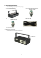
2 Product Inspection and Preparation 2.1 Confirmation of product packaging Confirm the following five parts in your DT-329 packaging: 1. One (1) LED linear stroboscope 2. One (1) External input connector (7 pins) SRCN6A16-7P [JAE] 3. One (1) External output connector (3 pins) SRCN6A13-3P [JAE] 4. One (1) AC cable 5. Instruction Manual 2.2 Removal of protective sheet Remove protective sheet covering the operation panel.
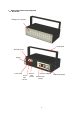
3 Names and functions of the components 3.
3.2 Operation panel 2 3 SE SET T 4 SE MODE POWER 1 PHASE+ 7 SE T T SE ×2 SE T T 9 5 1/2 SE PHASE- SE T T FLASH 6 SE T 8 FOCUS SE T 10 No. Key Function Instructions 1 POWER Power the unit on or off 2 MODE Select Internal /External/Parameter mode of operation 3 SET Unit change, Select parameter setting item, Store setting value. 4 ×2 Multiplies the flash rate/frequency by a factor of 2. 5 1/2 Divides the flash rate/frequency by a factor of 2.
3.3 LCD Display 3.3.1 Display Names and Descriptions Main data display Setting project Unit Sub data Auto Range Trigger Divider Edge Delay Deg Flash Time Mem AveLastMinMax min sec hHz Ave Last Min ○ ms 3.3.2 Main data display -Internal flashing mode: Displays flash rate. -External trigger mode: Display external trigger frequency. -*Parameter setting mode: Display LCD backlight setting (“P” or “LCD”) *Refer to section 4.5 for detail. 3.3.
3.3.
4 Function Instructions 4.1 Power on/off Turn on Main Power Switch, then press “POWER” key to turn on unit. The unit will begin to flash in internal mode and the display will indicate the flash rate (FPM = flashes per minute).
4.3 Internal flashing mode 4.3.1 Instruction for Internal flashing mode Flashing time (Hz shown) setting Flash indicator Internal flashing mode Auto Range Trigger Edge Deley Deg Flash Time Ave Last min sec hHz ○ Unit (min or Hz) Total phase shift angle 4.3.2 Changing Units of Measure in Internal Mode Press and release “SET” key to toggle between FPM and Hz measuring unit.
4.3.4 Flash rate and frequency “Internal Mode” Set the flash rate (frequency) by turning the center dial. Clockwise: Increase Counter-clockwise: Decrease For small adjustments, turn the dial slowly. For large adjustments, rotate the dial quickly. The flash rate and resolution differs according to measuring range. Refer to section 4.5.1 for details.
4.3.5 Multiply / Divide by 2 Function The flash rate or frequency can be doubled or halved by the “x2” and “½” keys on the operation panel. 1) Doubling the flash rate (x2) Press “x2” key to multiply the current flash rate by a factor 2 until the max flash rate is reached. Operation Indication FLASH ×2 Press and release Auto Range Trigger Edge Deley Deg Flash Time Ave Last Min Max Auto Range Trigger Ehidge Deley Deg Flash Time Ave Last Min Max min sec hHz ○ ○ ×2 Ex.
4.3.6 Phase Shift (Angle) Once "Frozen" virtual image is achieved via FPM=RPM, the phase shift function can advance or delay the flash so that the image appears to be rotating incrementally. Press “PHASE+” key or “PHASE-“ key to increment or decrement the phase shift angle by 3°. The display will show the cumulative angle of the phase shift.
Press the “RATIO” key. The current mode will start blinking for 5 seconds allowing modification at this point.
Operation Indication FLASH PHASE+ PHASE+ Press and release OR ・・・・ Auto Range Trigger Edge Deley Deg Flash Time Ave Last Min Max min sec hHz ○ Turn clockwise PHASE+ Auto Range Trigger Edge Deley Deg Flash Time Ave Last Min Max Auto Range Trigger Edge Deley Deg Flash Time Ave Last Min Max min sec hHz ○ または ○ Incremented 0.2°/ 360 ° Flash duration (FOCUS) 0.1°/ 360° min sec hHz Maximum 1.
4.4 External Trigger Mode This mode allows synchronization of the FPM with external signal input such as a sensor. See section 4.6 for details. Parameter settings are possible, like phase shift, delay time, flash duration, edge trigger. 4.4.
4.4.2.1 “Delay time” setting This can be set to 0~999 msec with a resolution of 1 ms. The internal calculation time of the unit is 60us, which results in the actual delay time being (Setting delay time) + 60us. st The DT-329 will begin flashing after the 1 trigger pulse. See timing chart below.
Press "PHASE+" key to select the delay time setting. Turn dial CW to increase and CCW to decrease.
4.4.2.2 “Delay angle” setting Set the delay angle from 0°to 360°in 1°increment s. The actual delay time is as follows: Delay angle setting 360° × Period of External Input + approx. 60us (Built-in) st While the DT-329 does not flash at the 1 trigger pulse as shown below in the timing chart.
Delay Angle setting will decrease from 359°(Max) t o 0°(Min) value for counter clockwise. The setting s will eventually go to 0°as when angle decreases from 359 °. ・・・・ Auto Range Trigger Edge Delay Deg Flash Time Ave Last Min Max Auto Range Trigger Edge Delay Deg Flash Time Ave Last Min Max min sec hHz ○ ms Turn counter clockwise Auto Range Trigger Edge Delay Deg Flash Time Ave Last Min Max min sec hHz ○ ms PHASE+ min sec hHz ○ ms Go to delay time setting 4.4.
4.5 Parameter Setting Instruction Press “MODE” until the LCD displays “P” (Parameter setting mode). Please refer to 4.2. Mode selection. Press the “SET” key to cycle between the various parameter settings available (range, trigger edge and delay time/delay angle). For more information regarding the various parameter settings, please refer to sections 4.5.2 through 4.5.4 below. Press the “MODE” key to store the settings and return to measuring modes. Note: “MODE” key must be pressed to store settings.
4.5.1 Measurement range setting The DT-329 has a selectable measuring range, which can be set in the Parameter mode setting. The range and resolution of this setting will be different for each measuring range, as indicated in the table below. Test unit FPM Hz Measuring range as Indicated in Parameter Settings 12,000 120,000 (range 60.0 - 12,000.0) (range 60 - 120,000) 200 2,000 (range 1.000 - 200.00) (range 1.00 - 2000.
Operation Expression FLASH PHASE+ Press and release Auto Range Trigger Edge Deley Deg Flash Time Ave Last Min Max FLASH PHASE+ min sec hHz Or Auto Range Trigger Edge Deley Deg Flash Time Ave Last Min Max min sec hHz ○ ms Turn clockwise ○ ms Measuring range set to “1 – 2000 Hz” Measuring range set to “1 – 200 Hz” FLASH PHASEPress and release Auto Range Trigger Edge Deley Deg Flash Time Ave Last Min Max min sec hHz FLASH PHASEOr ○ ms Turn counter clockwise Auto Range Trigger Edge Deley Deg F
Press the “SET” key to cycle to the Trigger Edge setting parameter mode. To set the trigger edge as “Down edge”, press “PHASE -“key or turn the dial clockwise. To set the trigger edge as “Up edge”, press “PHASE +” key or turn the dial counter clockwise.
4.5.3 Delay setting Delay time and angle setting will allow the flash to be delayed after an external pulse is sensed by the unit. The Parameter setting mode: Press “PHASE +” and “PHASE -“ key, to select between delay time and delay angle. 4.5.3.1 Delay time setting Selecting Delay time from an external pulse input to LED flashing can be set in the range of 0 – 999 msec, with a resolution of 1msec. For details, please refer to “4.4.2 Flash delay setting”.
4.5.3.2 Delay angle setting The delay angle can be set from 0°to 360°by 1°in crements. Delay angle setting increases as the dial turns right, and decreases as it turns left. Delay angle events to zero when set below 0°(min) or 360°(max).
4.6 Connector of External input/output 4.6.1 Connector Pin Assign External Input Pin No. Signal Name Contents 1 +12V +12V power supply output 2 G12 Ground of power supply output 3 TRG_IN External pulse input 4 IN_COM Common of External pulse input 5 NC 6 NC 7 FG DT-329 side: Accessory: Frame ground SRCN2A16-7S SRCN6A16-7P [JAE] [JAE] External Output Pin No.
4.6.3 External pulse output The unit will also output a signal that is related to the flash rate of the unit. This signal can be used to control additional stroboscopes so that each flashes at the same rate or to send a pulse to data collectors. External circuit: Open collector output, Voltage below DC30V, Current below 30mA Output pulse width: Approx. 200us [Output circuit] [Output time] Photocoupler (The same with TLP127 Toshiba made) Flashing 1pin External pulse output (36V) 2pin Approx.
5 Specifications Model Number DT-329 Units of measure FPM (flashes per minute) or Hz (frequency) Measuring range 1 - 2,000Hz 60 - 120,000 FPM Accuracy Resolution of flash rate setting in internal mode +/-0.02% (at 73°F [23°C]) Unit; Hz Unit; FPM Flashing time (Duty) Mode Internal External trigger Measuring range: 1-200 Hz Measuring range: 1-2000 Hz Measuring range: 60 - 12,000 FPM Measuring range: 60 - 120,000 FPM 0.
Display LCD 6 digits (main), 5 digits (sub) Flashing part Back light Flash Source Life time (Flashing “Setting item”, “Unit” Yellow green LED Super High Brightness White LED 5500K (typ) More than 1500 hours (approx.
13.39” 29 3.94” 100mm 340mm 6.02” 370mm 153mm 1.18” 7.28” 40mm 1.57” 30mm 185mm 6 Dimensions 14.