
Operator`s manual

9
Edger Blades
Check the edger blades condition frequently. If an edger blade’s performance
changes suddenly, stop the engine and check the blade for cracks or other dam-
age. Replace a damaged edger blade IMMEDIATELY!
WARNING!
Never repair a damaged edger blade by welding, straightening or by modi-
■
fying its shape. An altered edger blade may break during operation, result-
ing in serious personal injury.
The Multipurpose Edger Tool is designed for use with a single, bar-type
■
blade only.
Blades are not interchangeable between Shindaiwa edgers and brush
■
cutter models. Operating any machine with a blade or attachment not
approved for that unit can be hazardous and may cause serious injury.
A
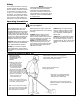
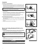
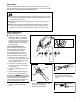
Remove the shaft bolt (A), bolt ■
guard (B), holder A (C), blade (D),
holder B (E), and the output shaft
collar (F). Press new grease into the
gearcase (G) until the old grease
has been pushed out. Use only lith-
ium-base grease.
Gearcase lubrication
50-hour Maintenance
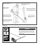
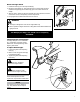
Lubricate the Flexible Shaft
Lack of lubrication will cause rapid
wear to the exible shaft and also
to the shaft tube liner, resulting
in increased vibration and greatly
decreased service life. Remove and
lubricate the exible shaft as follows:
With the unit on a clean, at sur-1.
face, loosen the coupler screw knob
(H). The spring-loaded coupler pro-
tector (I) should pop up.
Press down on the latch (J) with 2.
your nger or thumb. This releases
the coupler lock.
Pull the tool assembly out of the 3.
coupler.
Pull the exible shaft and bushing 4.
(K) from the shaft tube assembly.
NOTE:
For extended shaft life, the exible
cable should be reversed end-for-end
during the reinstallation process.
Clean the shaft thoroughly in sol-5.
vent and dry with a clean shop
towel.
26025
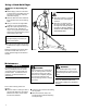
Inspect the Gearcase Protector
The metal gearcase protector (p/n
72958-16210) is installed to protect the
gearcase flange from damage when
working close to sidewalks or other
abrasive surfaces, and should be
routinely inspected for damage or
excessive wear. See Figure 15.
Lubricate the Flexible Shaft
Gearcase Protector
(p/n 72958-16210)
When replacing the protector,
inspect to be sure that both of the
protector mounting screws are firmly
tightened and each screw is locked in
place with a nut as shown in Figure 16.
Nut
Figure 16
50-hour Maintenance (Cont)
1285
MAINTENANCE
15
Figure 13
Figure 14
6. Coat the entire length of the shaft
with Shindaiwa Premium Gearcase
Lube (or equivalent).
7. Renstall the flexible shaft.
8. Reinstall the bushing. Push it into
the outer tube until it bottoms
against the collar on the flexible
shaft.
Lack of lubrication will cause rapid
wear to the flexible shaft and also to
the shaft tube liner, resulting in
increased vibration and greatly
decreased service life. Remove and
lubricate the flexible shaft as follows:
See Figure 13.
Figure 15
Latch
Latch
Protector
Coupler
Screw
Knob
1. With the unit on a clean, flat
surface, loosen the coupler screw
knob. The spring-loaded coupler
protector should pop up.
2. Press down on the latch with your
finger or thumb. This releases the
coupler lock. See Figure 9.
3. Pull the tool assembly out of the
coupler.
4. Pull the flexible shaft and bushing
from the shaft tube assembly. See
Figure 14. Clean the shaft thor-
oughly in solvent and dry with a
clean shop towel.
5. Inspect the flexible shaft carefully,
and replace if worn or damaged.
NOTE
Always replace the liner if the flexible
shaft is being replaced.
1281
Flexible Shaft
65010-94010_MLE230_07LP 11/21/01, 11:19 AM16
26025
Inspect the Gearcase Protector
The metal gearcase protector (p/n
72958-16210) is installed to protect the
gearcase flange from damage when
working close to sidewalks or other
abrasive surfaces, and should be
routinely inspected for damage or
excessive wear. See Figure 15.
Lubricate the Flexible Shaft
Gearcase Protector
(p/n 72958-16210)
When replacing the protector,
inspect to be sure that both of the
protector mounting screws are firmly
tightened and each screw is locked in
place with a nut as shown in Figure 16.
Nut
Figure 16
50-hour Maintenance (Cont)
1285
MAINTENANCE
15
Figure 13
Figure 14
6. Coat the entire length of the shaft
with Shindaiwa Premium Gearcase
Lube (or equivalent).
7. Renstall the flexible shaft.
8. Reinstall the bushing. Push it into
the outer tube until it bottoms
against the collar on the flexible
shaft.
Lack of lubrication will cause rapid
wear to the flexible shaft and also to
the shaft tube liner, resulting in
increased vibration and greatly
decreased service life. Remove and
lubricate the flexible shaft as follows:
See Figure 13.
Figure 15
Latch
Latch
Protector
Coupler
Screw
Knob
1. With the unit on a clean, flat
surface, loosen the coupler screw
knob. The spring-loaded coupler
protector should pop up.
2. Press down on the latch with your
finger or thumb. This releases the
coupler lock. See Figure 9.
3. Pull the tool assembly out of the
coupler.
4. Pull the flexible shaft and bushing
from the shaft tube assembly. See
Figure 14. Clean the shaft thor-
oughly in solvent and dry with a
clean shop towel.
5. Inspect the flexible shaft carefully,
and replace if worn or damaged.
NOTE
Always replace the liner if the flexible
shaft is being replaced.
1281
Flexible Shaft
65010-94010_MLE230_07LP 11/21/01, 11:19 AM16
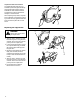
Coat the entire length of the shaft 6.
with lithium-base grease.
Renstall the exible shaft.7.
Reinstall the bushing. Push it into 8.
the outer tube until it bottoms
against the collar on the exible
shaft.
26025
Inspect the Gearcase Protector
The metal gearcase protector (p/n
72958-16210) is installed to protect the
gearcase flange from damage when
working close to sidewalks or other
abrasive surfaces, and should be
routinely inspected for damage or
excessive wear. See Figure 15.
Lubricate the Flexible Shaft
Gearcase Protector
(p/n 72958-16210)
When replacing the protector,
inspect to be sure that both of the
protector mounting screws are firmly
tightened and each screw is locked in
place with a nut as shown in Figure 16.
Nut
Figure 16
50-hour Maintenance (Cont)
1285
MAINTENANCE
15
Figure 13
Figure 14
6. Coat the entire length of the shaft
with Shindaiwa Premium Gearcase
Lube (or equivalent).
7. Renstall the flexible shaft.
8. Reinstall the bushing. Push it into
the outer tube until it bottoms
against the collar on the flexible
shaft.
Lack of lubrication will cause rapid
wear to the flexible shaft and also to
the shaft tube liner, resulting in
increased vibration and greatly
decreased service life. Remove and
lubricate the flexible shaft as follows:
See Figure 13.
Figure 15
Latch
Latch
Protector
Coupler
Screw
Knob
1. With the unit on a clean, flat
surface, loosen the coupler screw
knob. The spring-loaded coupler
protector should pop up.
2. Press down on the latch with your
finger or thumb. This releases the
coupler lock. See Figure 9.
3. Pull the tool assembly out of the
coupler.
4. Pull the flexible shaft and bushing
from the shaft tube assembly. See
Figure 14. Clean the shaft thor-
oughly in solvent and dry with a
clean shop towel.
5. Inspect the flexible shaft carefully,
and replace if worn or damaged.
NOTE
Always replace the liner if the flexible
shaft is being replaced.
1281
Flexible Shaft
65010-94010_MLE230_07LP 11/21/01, 11:19 AM16
B
C
D
E
F
G
K
I
J
H