SHINDAIWA OWNER’S/0PERATOR'S MANUAL EB501 BLOWER High Performance WARNING! Minimize the risk of injury to yourself and others! Read this manual and familiarize yourself with the contents. Always wear eye and hearing protection when operating this unit. Minimize the risk of injury: Read this manual and familiarize yourself with its contents. Part Number 68232-94011 Rev.
INTRODUCTION IMPORTANT! Before using this product, consult local regulations concerning noise restrictions and hours of operation! The Shindaiwa EB501 has been designed and built to deliver superior performance and reliability without compromise to quality, comfort, safety, or durability. Shindaiwa high performance engines represent the leading edge of 2-cycle engine technology, and deliver exceptionally high power at remarkably low displacement and weight.
ATTENTION STATEMENTS This manual contains special “attention statements” surrounded by boxes and preceded by the triangular Attention Symbol. WARNING! A statement preceded by the word “WARNING” contains information that should be acted upon to prevent serious bodily injury. CAUTION! A statement preceded by the word “CAUTION” contains information that should be acted upon to prevent damaging your machine.
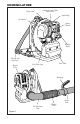
NOMENCLATURE Volute Case Carburetor with Choke and Primer Spark Plug Air Cleaner Starter Handle Exhaust Outlet Throttle and Stop Lever Engine Cover Fuel Tank Fuel Filler Cap Handgrip 48002 90° Discharge Tube Figure 1 3 Flexible Tube Swivel Tube
SPECIFICATIONS Model................................................................................................................... EB501 Dimensions (L x W x H)...............................................................330 x 375x 475 mm Engine Type.................... 2 cycle, catalyst, air cooled gas engine, vertical-cylinder Bore & Stroke.............................................................. 41 x 33 mm (1.6 x 1.3 inches) Displacement.........................................................
ASSEMBLING THE BLOWER (continued) 115mm Clamp Nut Swivel Tube Handgrip Bolt Washer 85mm Clamp 48002A 90° Discharge Tube 90° Discharge Tube Flexible Tube 100mm Clamp Handgrip Flexible Tube Swivel Tube Straight Tube Nozzle Tube 48003 Figure 2 6. Grasp the straight tube as shown, and push the tube over the swivel tube locking pins (right). See figure 3. Tube Assembly Align the lock pins with the lock slots, and push the tubes together. 7.
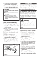
MIXING FUEL Fuel Requirements n Use only fresh, clean fuel. n Use only fuel with an octane rating of 87 or above. n Mix all fuel with ISO EGD or JASO FC class 2-cycle Engine Oil at a gasoline/oil ratio of 50:1 (1 gallon gasoline to 2.6 oz. mixing oil). CAUTION! Use of mixing oil other than ISO EGD or JASO FC rated oil can lead to exessive carbon deposits.
FILLING THE FUEL TANK Remove the Fuel Filler Cap 1. Place the blower upright on the ground or on a sturdy work surface and wipe any debris from around the fuel cap. 2. Remove the fuel cap. See figure 4. 3. Fill the tank with clean, fresh fuel (see page 6). 4. Replace the cap and wipe away any spilled fuel before starting the blower engine.
STARTING AND STOPPING THE BLOWER WARNING! Danger from rotating impeller! The impeller will rotate whenever the blower is operating! Never operate this blower unless the intake cover and blower tubes are properly installed and in good working order! Danger from thrown dust or debris! Always wear eye and respiratory protection when operating this machine! Never direct the blower stream toward people or animals! Never operate this blower unless all controls are properly installed and in good working order.
5. As the starter engages, pull the starter handle upward rapidly. 6. If necessary, repeat Steps 4 and 5 2–3 times until the engine starts. CAUTION! The recoil starter can be damaged by abuse! n Never pull the starter cord to its full length. n Always engage the starter before cranking the engine. Always rewind the starter cord slowly. IMPORTANT! If the engine continues to run with the throttle lever in the “off” position, stop the engine by moving the choke control UP to the fully closed position.
ADJUSTING ENGINE IDLE SPEED 1. Start the engine by following the procedures described on the preceding pages. Make sure the thottle lever is in the "idle" position. Idle Decrease Idle Increase 2. Run the engine at idle speed until operating temperature is reached (2-3 minutes). 3. Loosen the throttle cable locknut. See figure 9. 4. Turn the cable adjuster in or out until the engine idles smoothly at approximately 2500-3000 rpm.
ADJUSTING THE HARNESS The Shindaiwa EB501 Blower features an advanced harness system that helps ensure maximum operator comfort and ease of operation. The adjusting strap lets the user determine how far apart the upper harness loops are positioned. Easy to customize for maximum comfort. n The shoulder harness is filled with soft padding for reduced operator fatigue. n The simplified adjustment system makes it easy to match the harness to every body size and type. See figure 10.
USING THE BLOWER THINK SAFETY! OPERATING TIPS In the hands of an experienced operator, the EB501 can efficiently move a wide variety of debris ranging from grass clippings to gravel.
ROUTINE MAINTENANCE EVERY 10 HOURS IMPORTANT! (more frequently in dusty conditions) Remove the Element Maintenance, replacement or repair of emission control devices and sysCover Latch tems may be performed by any repair establishment or individual.
EVERY 10/15 HOURS to remove 48017 0.024" (0.6mm) gap EVERY 50 HOURS (more frequently if reduced performance is noted) n INSPECTION Inspect the entire blower and tubes for damage, including loose or missing components, and repair as necessary. n SPARK PLUG Replace the spark plug with a Champion CJ8 or equivalent, gapped to 0.024 inch (0.6mm). Champion CJ8 Spark Plug Wire Hook 48014 Figure 14 1. Use the spark plug wrench to remove the spark plug (turn counterclockwise to remove). See figure 13. 2.
135-HOUR MAINTENANCE Ever y 135 hours of operation, remove and clean the muffler.
STORAGE (30 days or longer) n CLEANING Thoroughly clean the blower exterior. n INSPECTION Inspect the entire blower and tubes for damage, including loose or missing components, and repair as necessary. n LUBRICATION Remove the spark plug, and then pour approximately 1/4-oz of 2-cycle oil into the cylinder through the spark plug hole. Before reinstalling the spark plug, pull the recoil starter gently 2–3 times to distribute the oil over the cylinder walls.
TROUBLESHOOTING GUIDE ENGINE DOES NOT START What To Check Possible Cause Remedy Faulty recoil starter. Fluid in the crankcase. Internal damage. Consult with an authorized servicing dealer. NO Loose spark plug. Excess wear on cylinder, piston, rings. Tighten and re-test. Consult with an authorized servicing dealer. NO Fuel/mixture incorrect, stale, contaminated. Refill with fresh fuel of the correct mixture (gasoline and ISO EGD or JASO FC class 2-cycle Engine Oil).
TROUBLESHOOTING GUIDE (continued) LOW POWER OUTPUT What To Check Is the engine overheating? Possible Cause Operator is overworking the machine. Remedy Use lower throttle setting. Improper fuel/oil ratio. Refill with fresh fuel of the correct mixture (gasoline and ISO EGD or JASO FC class 2-cycle Engine Oil, 50:1 ratio. Fallen leaves or dust on the intake cover. Clean the intake cover. Fan, fan cover, or cylinder Clean, repair or replace as fins are dirty or damaged. necessary.
TROUBLESHOOTING GUIDE (continued) ADDITIONAL PROBLEMS What To Check Engine is knocking. Poor acceleration. Egine difficult to shut off. 19 Possible Cause Remedy Overheating condition. Idle engine until cool; find reason for overheat. Improper fuel. Check fuel octane rating. Check for presence of alcohol in fuel. Refuel as necessary. Carbon deposits in combustion chamber and/or exhaust port. Consult with an authorized servicing dealer. Clogged air cleaner element. Clean the element.
TROUBLESHOOTING GUIDE (continued) ADDITIONAL PROBLEMS What To Check Engine stops abruptly. Excessive vibration. Engine overspeeding. Possible Cause Remedy Throttle lever is the ''OFF'' position. Move throttle lever to the run position and reststart. Fuel tank empty. Refuel. Clogged fuel filter. Replace fuel filter. Water in the fuel. Drain; replace with clean fuel. Replace fuel filter. Shorted spark plug or loose terminal. Clean or replace spark plug; tighten the terminal. Ignition failure.
The following statement only applies to United States and its territories Shindaiwa Corporation Federal Emission Design And Defect Limited Warranty Utility And Lawn And Garden Engines Shindaiwa Corporation warrants to the initial purchaser and each subsequent owner, that this utility equipment engine (herein engine) is designed, built and equipped to conform at the time of initial sale, to all applicable regulations of the U.S.
(unless they were made by the dealer or service center authorized by Shindaiwa Corporation during a warranty repair), alteration, accident, failure to use the recommended fuel and oil, or not performing required maintenance services, (b) the replacement parts used for required maintenance services, (c) consequential parts used for required maintenance services, (d) diagnosis and inspection fees that do not result in eligible warranty service being performed, and (e) any non-authorized replacement part,
Shindaiwa Inc. 11975 S.W. Herman Rd. Tualatin, Oregon 97062 USA Telephone: 503 692-3070 Fax: 503 692-6696 www.shindaiwa.com Shindaiwa Corporation Head Office: 6-2-11, Ozuka-Nishi Asaminami-Ku, Hiroshima 731-3167, Japan Telephone: 81-82-849-2220 Fax: 81-82-849-2481 © 2006 Shindaiwa, Inc. Part Number 68232-94011 Printed in Japan Shindaiwa is a registered trademark of Shindaiwa, Inc. Specifications subject to change without notice.