SHINDAIWA GRASS TRIMMER TO BLADE CONVERSION INSTRUCTIONS Model 89291B For Trimmer T242 WARNING! Minimize the risk of injury to yourself and others! Read the Owner's/Operator's manual originally supplied with the unit that is being upgraded and familiarize yourself with the contents. Always wear eye and hearing protection when operating your unit.
Introduction These are instructions to convert a grass trimmer to a blade capable unit. This is not an Owner's/Operator's manual. Information on how to operate and maintain the unit can be found in the Owner's/Operator's manual for the unit you are converting. Note this kit is supplied with a cutting attachment shield that has been redesigned to provide better visibility and a larger cutting swath when used as a grass trimmer.
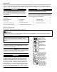
Safety Labels IMPORTANT! Safety and Operation Information Labels: Make sure all information labels are undamaged and readable. Immediately replace damaged or missing information labels. A new label is provided in this kit and additional labels are available from your local authorized Shindaiwa dealer. Prior to installing the new label, Remove old label and clean the outer tube with rubbing alcohol or similar cleaner.
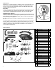
Blade Thrust Eleven O’Clock ‘Blade thrust’ is a sudden sideways or backward motion of the brushcutter. Such motion may occur when the blade jams or catches on an object such as a sapling tree or tree stump. BE CONSTANTLY ALERT FOR BLADE THRUST AND GUARD AGAINST ITS EFFECTS! DO NOT C UT Blade Rotation Barrier Bar A brushcutter’s barrier bar helps prevent the operator from moving forward, or the unit moving rearward, thus preventing inadvertent bodily contact with the blade.
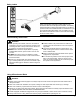
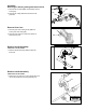
Assembly Removing the Existing Cutting Attachment Shield 1. Remove the four bolts (MM), bracket (NN), and two shims (OO). 2. Remove the cutting attachment shield from the gearcase. MM NN OO OO Remove Gear Case 1. Remove gear case locating screw (RR) and loosen gear case clamp (SS). 2. Remove gear case from outer tube. Retain all parts for future use. RR SS Remove Handle Assembly T242 with 1-screw Handle 1. Remove handle assembly. Retain all parts for future use.
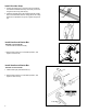
Install Shoulder Strap G LL 1. Position the hanger (G) on the outer tube (LL) between the handle and throttle assembly and loosely secure the hanger with the nut (F) and bolt (H). 2. Adjust the shoulder strap so the shoulder pad rests comfortably on the left shoulder and the cutting path of the cutting attachment is parallel to the ground. Tighten hanger bolt (H). F,H Install Handle and Barrier Bar T242 with 1-screw Handle 1. Install Handle and Barrier Bar (B). 2.
Install Gear Case RR 1. Install gear case onto outer tube. Align locating hole on gear case with locating hole in tube. 2. Install locating bolt (RR) and tighten clamp bolt (SS). SS Install Debris Shield Assemble the Cutting Attachment Shield to the Outer Tube. 1. Insert the cutting attachment shield (K) between the outer tube and the cutting attachment mounting plate (QQ). K N L 2.
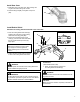
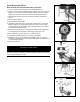
Install Brushcutter Blade NOTE: There are four gear case configurations. Select one of the following instructions to properly install a metal blade. Gear Case #1 with notched flange: FF DD GG 1. Turn the unit over so that the gear case output shaft faces UP. 2. Align the hole in the holder (GG) with the notch in the gearcase flange, and then temporarily lock the output shaft by inserting a hex wrench (DD) through both holes. 26107 3.
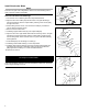
Install Brushcutter Blade Gear Case #2 with side-mounted locking tool hole: FF 1. Turn the unit over so that the gear case output shaft faces UP. 2. Align the notch in trimmer head holder (GG) with the notch in the gear case flange. Lock the holder and output shaft by inserting a hex wrench (DD) through the locking hole in the gear case and into the aligned notches. GG 3. While holding the hex wrench turn the trimmer head (FF) clockwise to remove. 4. Remove the hex wrench. DD 5.
Install Brushcutter Blade Gear Case #3 with side-mounted locking tool hole and grooved output shaft: FF 1. Turn the unit over so that the gear case output shaft faces UP. GG 2. Align the notch in trimmer head holder (GG) with the notch in the gear case flange. Lock the holder and output shaft by inserting a hex wrench (DD) through the locking hole in the gear case and into the aligned notches. 3. While holding the hex wrench turn the trimmer head (FF) clockwise to remove. DD 4. Remove the hex wrench.
Install Brushcutter Blade FF Gear Case #4 with side-mounted locking tool hole, grooved output shaft, and gear case cover: GG 1. Turn the unit over so that the gear case output shaft faces UP. 2. Lock gear case by inserting a 4mm hex wrench (DD) into locking hole. Apply light pushing force to wrench while turning splined power output shaft. Continue turning until wrench engages locking notch on underside of blade fixture (T). Hold wrench securely to prevent output shaft from turning. 3.
Consumer Product Support If you require assistance or have questions concerning the application, operation or maintenance of this product you may call the Shindaiwa Consumer Product Support Department at 1-877-986-7783 from 8:30 am to 4:30 pm (Central Standard Time) Monday through Friday. Before calling, please know the model and serial number of your unit. ECHO Incorporated. 400 Oakwood Road Lake Zurich, IL 60047-1564 U.S.A. Telephone: 1-877-986-7783 Fax: 1-847-540-8416 www.shindaiwa.