
Operator`s manual


10
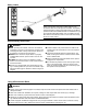
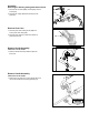
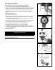
1. Turn the unit over so that the gear case output shaft faces UP.
2. Align the notch in trimmer head holder (GG) with the notch in the gear case
ange. Lock the holder and output shaft by inserting a hex wrench (DD)
through the locking hole in the gear case and into the aligned notches.
3. While holding the hex wrench turn the trimmer head (FF) clockwise to
remove.
4. Remove the hex wrench.
5. Remove trimmer head holder.
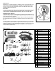
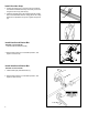
6. Align tabs on gear case cover (S) with slots in retaining lip on gear case.
NOTE: Position cover to align locking holes (S1) when cover is rotated
counterclockwise. Secure cover to gear case with (1) M5 x 12 mm bolt w/
lock washer and at washer (KK).
7. Place upper blade xture (T) on splined power output shaft. Blade xture
must engage splines and t over outside edge of gear case cover.
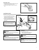
8. Place blade (EE) over mounting arbor on blade xture (T). Install clip (W)
in shaft groove to retain blade. Place lower blade holder (X) on output shaft
(HH), covering clip. Holder must t at against blade and completely cover
clip.
9. Install bolt guard (Y) on the output shaft.
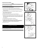
10.Install the 7x26 mm blade retaining bolt with at washer (Z). Using the
combination spark plug wrench/screwdriver, tighten the bolt rmly in a
counterclockwise direction.
11.Remove hex wrench.
The unit should now be completely assembled
and ready for use with a blade.
IMPORTANT!
Units with adjustable carburetors must be readjusted for blade use, otherwise
serious engine damage can occur.
Install Brushcutter Blade
X
Z
Y
EE
W
HH
DD
GG
T
W
Y
X
Z
Gear Case #3 with side-mounted locking tool hole and grooved
output shaft:
FF
S
S1
KK