SHINDAIWA OWNER’S/OPERATOR’S MANUAL MULTIPURPOSE POLE PRUNER ATTACHMENT 78701 For Models T230, T231, AH230, AH231, PB230 Minimize the risk of injury to yourself and others! Read this manual and familiarize yourself with the contents. Always wear eye and hearing protection WARNING! when operating this unit.
Introduction The Shindaiwa Pole Pruner Attachment is designed and built to deliver superior performance and reliability without compromise to quality, comfort, safety or durability. As an owner/operator, you'll soon discover for yourself why Shindaiwa is simply in a class by itself! While every attempt has been made to provide the latest information about your Shindaiwa product, there may be some differences between your attachment and what is described here.
Safety This machine operates at very high speeds and has the potential to do serious damage if misused, abused or mishandled. To reduce the risk of injury, you must maintain control at all times, and observe all safety precautions during operation. Never permit a person without training or instruction to operate this machine! NOTE: For specific maintenance and safety information about your T230/231, AH230/231, or PB230, consult the owner's manual provided with it.
Operating the Pruner WARNING! Always wear eye and hearing protection. Shindaiwa recommends wearing a face shield as additional face and eye protection. To avoid the chance of serious injury or death, follow these safety precautions during operation: Keep bystanders at least 50 feet (15 meters) away from the operating pruner to reduce the risk of being cut by moving saw chain or struck by falling objects or thrown debris.
Safety Labels IMPORTANT! Safety and Information Labels: Make sure all safety and information labels are undamaged, readable and up to date. Immediately replace damaged or missing labels. This Attachment comes with safety labels shipped loose in the box. Attach these safety labels. New labels are available through your local authorized Shindaiwa dealer. Product Description Using the illustration as a guide, familiarize yourself with your machine and its various components.
Prior To Assembly Before assembling, make sure you have all the components required for a complete unit: Throttle Grip w/interlock IMPORTANT! The terms “left”, “left-hand”, and “LH”; “right”, “right-hand”, and “RH”; “front” and “rear” refer to directions as viewed by the operator during normal operation. Scabbard Owner's/Operator's manual Gearcase assembly Assembly Tool (s) Guide Bar Safety Labels Saw Chain Carefully inspect all components making sure they are not damaged.
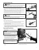
Installing Throttle Grip ■ B WARNING! Failure to replace the standard throttle grip with the provided interlock throttle grip could permit unintentional acceleration, which could cause serious injuries or death. A 1. Place the T230 or PB230 outer tube assembly on a clean, flat surface. 2. Loosen the three screws (A) that hold the throttle trigger assembly to the outer tube. 3. Slide the trigger assembly down the tube, several inches away from the rubber grip.
Reconnecting the Throttle Cable, Switch Wires Connect The Throttle Cable. 1. Loop the ribbed cable assembly to the top left side of the engine. Confirm that the black ground wire (A) (with an eyelet on the end) is located between the two cable adjuster nuts (B). B D 2. Connect the Z-shaped end of the throttle cable (C) to the throttle lever on top of the carburetor. C 3. Turn the cable adjuster nuts sufficiently for the throttle cable to fit in the notch (D) on the fan cover.
2. Adjust the throttle cable nuts until you achieve a free play on the throttle trigger of about 1/4 inch. IMPORTANT! Make sure the stop switch wires do not interfere with throttle functions. Reposition wires if necessary. 3. When 1/4-inch of free play is achieved, securely tighten the two 10mm throttle cable nuts. When the throttle cable is correctly adjusted, and the throttle trigger is fully depressed (full throttle), the throttle will contact the stop on the throttle body (F).
Installing the Caution Labels WARNING! ■ The provided labels offer important safety information about pole pruners. Do not operate, or allow others to operate, this machine unless the labels are properly installed. 1. Clean outer tube so the labels will adhere properly. 2. Peel the backing off the multiple warning label and attach below similar label on lower part of outer tube. Make sure label faces up and that it is legible from the operator's position. 3.
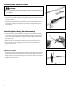
Installing and Adjusting the Bar and Chain Installing The Chain B WARNING! Never attempt to install, replace, or adjust the chain with the engine running. WARNING! A The saw chain is very sharp. Wear gloves to protect your hands when handling. NOTE: For the longest chain life, let new or replacement chain loops soak in oil overnight before installation. D 1. Using the small end of the plug wrench, remove the sprocket cover nut (A) (turn counterclockwise to remove) and remove the sprocket cover (B).
Adjusting the Chain WARNING! Never attempt to install, replace, or adjust the chain with the engine running. WARNING! The saw chain is very sharp. Wear gloves to protect your hands when handling. A CAUTION! A loose chain can jump off the guide bar causing damage to the chain and associated equipment. Always make sure the chain is properly adjusted; check more often when you are breaking in a new chain.
NOTE: Very little visible oil on the saw chain will provide sufficient lubrication. Adjust the pump as follows: 1. Stop the engine and make sure the stop switch is in the OFF position. 2. Place the unit on its side with the oil reservoir (D) up. 3. Using a screwdriver, turn the oil flow rate adjustment screw (E) in the desired direction: • clockwise–decrease lubrication. • counter clockwise–increase lubrication.
Using the Pole Pruner This machine is designed especially for cutting branches. Never use this machine for any other purpose. Never try to cut stones, metals, plastics, or any other hard objects. Cutting On A Work Platform: Standard Cut: The most convenient working position is a tool angle of 60°, but any other angle may be used to suit the situation. The unit’s long reach enables cutting to be performed next to the trunk without the risk of the work platform damaging other branches.
Maintenance IMPORTANT! For detailed maintenance information about your T230/231, AH230/231, or PB230, consult the owner's manual that was provided with it. If it has been lost or misplaced, contact Shindaiwa for a replacement. WARNING! Before performing any maintenance, repair, or cleaning work on the unit, make sure the engine and cutting attachment are completely stopped. Disconnect the spark plug wire before performing service or maintenance work.
Sharpening the Chain ■■ When the cutting edges of the blade become dull, they can be re-sharpened with a few strokes of a file. ■■ In order to keep the blade in balance, all cutting edges must be sharpened equally. ■■ In addition, inspect the chain for correct adjustment (more frequently with a new chain). The chain should feel snug but still pull freely. Refer to adjustment procedures. CAUTION! Keep the chain sharp and properly adjusted. 30° WARNING! The saw chain is very sharp.
Troubleshooting Guide Symptom Excessive vibration. Cutting attachment will not move. Cutting attachment moves at engine idle. ADDITIONAL PROBLEMS Possible Cause Remedy Warped or damaged attachment. Inspect and replace attachment as required. Loose gearcase. Tighten gearcase securely. Bent main shaft/worn or damaged bushings. Inspect and replace as necessary. Shaft not installed in powerhead or gearcase. Inspect and reinstall as required. Broken shaft.
NOTES 18
NOTES 19
Servicing Information Parts/Serial Number Genuine Shindaiwa Parts and Assemblies for your Shindaiwa products are available only from an Authorized Shindaiwa Dealer. When you do need to buy parts always have the Model Number, Type and Serial Number of the unit with you. You can find these numbers on the engine. For future reference, write them in the space provided below. Model No. _____________ SN.