SHINDAIWA OWNER’S/OPERATOR’S MANUAL C242 Brushcutter WARNING! Minimize the risk of injury to yourself and others! Read this manual and familiarize yourself with the contents. Always wear eye and hearing protection when operating this unit. WARNING! The engine exhaust from this product contains chemicals known to the State of California to cause cancer, birth defects or other reproductive harm.
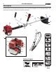
C242 Brushcutter Introduction The Shindaiwa 242 Series hand held power equipment has been designed and built to deliver superior performance and reliability without compromise to quality, comfort, safety or durability. Shindaiwa engines represent the leading edge of high-performance engine technology, delivering exceptionally high power with remarkably low displacement and weight. As an owner/operator, you’ll soon discover for yourself why Shindaiwa is simply in a class by itself! ECHO Inc.
C242 Brushcutter 3 Attention Statements Throughout this manual are special “attention statements”. DANGER! A statement preceded by the triangular attention symbol and the word “DANGER” contains information that should be acted upon to prevent serious injury or death. WARNING! A statement preceded by the triangular attention symbol and the word “WARNING” contains information that should be acted upon to prevent serious bodily injury.
C242 Brushcutter 4 Safety Instructions Personal Condition and Safety Equipment WARNING! Users of this product risk injury to themselves and others if the unit is used improperly and/or safety precautions are not followed. Proper clothing and safety gear must be worn when operating unit. Physical Condition Your judgment and physical dexterity may not be good: • if you are tired or sick, • if you are taking medication, • if you have taken alcohol or drugs.
C242 Brushcutter Safety Instructions Equipment WARNING! Use only ECHO Inc. attachments. Serious injury may result from the use of a non-approved attachment combination. ECHO Inc. will not be responsible for the failure of cutting devices, attachments or accessories which have not been tested and approved by ECHO Inc. Read and comply with all safety instructions listed in this manual. ■■Check unit for loose/missing nuts, bolts, and screws. Tighten and/or replace as needed.
C242 Brushcutter 6 Safety Instructions Avoid Hot Surfaces Keep exhaust area clear of flammable debris. Avoid contact during and immediately after operation. WARNING! During operation the muffler or catalytic muffler and surrounding cover become hot. Always keep exhaust area clear of flammable debris during transportation or when storing, otherwise serious property damage or personal injury may result.
C242 Brushcutter 7 Emission Control (Exhaust & Evaporative) EPA 2010 and Later and/or C.A.R.B. TIER III The emission control system for the engine is EM (engine modification) and, if the second to last character of the Engine Family on the Emission Control Information label (sample below) is “C”, “K”, or “T”, the emission control system is EM and TWC (3-way catalyst). The fuel tank/fuel line emission control system is EVAP (evaporative emissions).
C242 Brushcutter 8 Description Locate the safety label(s) on your unit. Make sure the label(s) is legible and that you understand and follow the instructions on it. If a label cannot be read, a new one can be ordered from your Shindaiwa dealer. See "Servicing Information" instructions for specific information. 13 12 17 14 15 11 18 16 19 24 10 20 22 23 21 READ THE OPERATOR’ S M ANUAL 2 1 3 WEAR HEARING AND ANSI Z8 7 .
C242 Brushcutter 9 Description 1 POWER HEAD - Includes the engine, clutch, fuel system, ignition system, intake and exhaust systems and recoil starter. 2 SPARK PLUG - Provides spark to ignite fuel mixture. 3 CHOKE LEVER - Is located on the air filter case. When starting a cold engine, move choke lever to COLD START position to close choke. Open choke by moving choke lever to RUN position).
C242 Brushcutter 10 Assembly This unit comes fully assembled with the exception of the handlebar, throttle assembly, debris shield, trimmer head, trimmer head spacer and drive shaft cushion. Install the handlebar 1. Use the 4 mm hex wrench to remove the lower cap retaining screws (A) from the handlebar bracket (C). Remove the cap (B) from the bracket. 2. Position the handlebar (D) on the main pipe (E) forward of Handle Positioning Label (F) as shown.
C242 Brushcutter 11 Assembly Connect throttle linkage 1. Move Choke Lever (A) to COLD START position (B) to close choke. This prevents dirt from entering the carburetor throat when the air filter is removed. Brush accumulated dirt from air filter area. 2. Loosen air filter cover knob (C) and remove the air filter cover (D). 3. Thread throttle cable adjuster (E) through throttle cable bracket (F), and insert the cable end into the swivel's slot (G) on the carburetor.
C242 Brushcutter 12 Assembly Install the debris shield assembly for use with a trimmer head 1. Place shim (J) on debris shield assembly (K) and insert between the main pipe (L) and mounting plate (M). R NOTE: It may be necessary to loosen the retaining nut (N) and clamp screw (O) to adjust mounting plate (M). 2. Fit shim (P) and bracket (Q) on main pipe (L). Install the four socket-head cap screws (R) and loosely tighten (finger tight). 3. Re-tighten clamp screw (O) and retaining nut (N). 4.
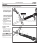
C242 Brushcutter 13 Assembly Install the Speed-Feed© trimmer head NOTE: This unit is shipped with Shaft Bolt (A), Bolt Guard (B), Holder (C), Clip (D) and Holder (E) installed. The shaft bolt is a LEFT-HAND thread. Remove it by turning CLOCKWISE! 1. Turn the trimmer over so that the gear case shaft bolt (A) faces UP. 2. Lock gear case by inserting a 4 mm hex wrench (F) into locking hole (G). 3. Apply light pushing force to wrench (F) while turning shaft bolt (A) counterclockwise. 4.
C242 Brushcutter 14 Assembly A Installing a blade WARNING! B Do not attach any blade to a unit without proper installation of all required parts. Failure to use the proper parts can cause the blade to fly off and seriously injure the operator and/or bystanders. 1. Turn the trimmer over so that the gear case shaft bolt (A) faces UP. 2. Lock gear case by inserting a 4 mm hex wrench (F) into locking hole (G). 3. Apply light pushing force to wrench (F) while turning shaft bolt (A) counterclockwise. 4.
C242 Brushcutter 15 Fuel WARNING! Alternative fuels, such as E15 (15% ethanol), E85 (85% ethanol) or any fuels not meeting ECHO Inc. requirements are NOT approved for use in Shindaiwa gasoline engines. Use of alternative fuels may cause performance problems, loss of power, overheating, fuel vapor lock, and unintended machine operation, including, but not limited to, improper clutch engagement.
C242 Brushcutter Fuel IMPORTANT! Spilled fuel is a leading cause of hydrocarbon emissions. Some states may require the use of automatic fuel shut-off containers to reduce fuel spillage. After use • DO NOT store a unit with fuel in its tank. Leaks can occur. Return unused fuel to an approved fuel storage container. Storage - Fuel storage laws vary by locality. Contact your local government for the laws affecting your area. As a precaution, store fuel in an approved, airtight container.
C242 Brushcutter 17 Starting a cold engine WARNING! The attachment will operate immediately when the engine starts, and could result in possible serious injury. Keep movable parts of the attachment away from objects that could become entangled or thrown, and surfaces that could cause loss of control. IMPORTANT! Engine ignition is controlled by a two position stop switch mounted on the throttle handle labeled, “I” for ON or START and “O” for OFF or STOP. 1.
C242 Brushcutter 18 Starting a warm engine A WARNING! The cutting attachment should not move at idle, otherwise serious personal injury may result. NOTE: If cutting attachment moves, readjust carburetor according to “Carburetor Adjustment: Adjusting Engine Idle” instructions in this manual or see your Shindaiwa Dealer. The starting procedure is the same as "Starting Cold Engine" except DO NOT move choke lever (B) to COLD START position (C), and do not depress throttle trigger to wide open position. 1.
C242 Brushcutter 19 Stopping the engine 1. Throttle Release throttle trigger (L) and allow engine to return to idle before shutting off engine. 2. Stop Switch Move stop switch (M) to STOP position. L M WARNING! If engine does not stop when stop switch is moved to STOP position, move choke lever to COLD START position, to close choke and stall engine. Have your Shindaiwa dealer repair stop switch before using unit again.
C242 Brushcutter 20 Operation Cutting Grass Units equipped with a trimmer head Your Shindaiwa unit may be equipped with one of several Shindaiwa trimmer head models, each with features for specific applications and/or operational requirements. For proper operation, always refer to the instructions accompanying the trimmer head being used. Available trimmer head styles include: ■■Semi-automatic. Trimmer line is advanced when the operator taps the trimmer head on the ground during operation. ■■Manual.
C242 Brushcutter 21 Operation Blades Keep blades sharp and check blade condition frequently. If a blade’s performance changes suddenly, stop the engine and check the blade for cracks or other damage. Replace a damaged blade IMMEDIATELY! WARNING! ■■Wear gloves to protect hands from sharp edges. ■■Always check the debris shield is properly installed and the debris shield extension is removed. ■■Always wear a shoulder strap or harness when operating this unit with a blade.
C242 Brushcutter 22 General Maintenance IMPORTANT! MAINTENANCE, REPLACEMENT OR REPAIR OF EMISSION CONTROL DEVICES AND SYSTEMS MAY BE PERFORMED BY ANY REPAIR ESTABLISHMENT OR INDIVIDUAL; HOWEVER, WARRANTY REPAIRS MUST BE PERFORMED BY A DEALER OR SERVICE CENTER AUTHORIZED BY ECHO INC. THE USE OF PARTS THAT ARE NOT EQUIVALENT IN PERFORMANCE AND DURABILITY TO AUTHORIZED PARTS MAY IMPAIR THE EFFECTIVENESS OF THE EMISSION CONTROL SYSTEM AND MAY HAVE A BEARING ON THE OUTCOME OF A WARRANTY CLAIM.
C242 Brushcutter 23 10-Hour Maintenance Every 10 hours of operation A B (more frequently in dusty or dirty conditions). 1. Move choke lever (A) to COLD START position (B),, to close choke. This prevents dirt from entering the carburetor throat when the air filter is removed. Brush accumulated dirt from air filter area. 2. Loosen the air filter cover knob (C) and remove the air filter cover (D). Brush dirt from inside cover. 3.
C242 Brushcutter 24 50-Hour Maintenance Every 50 hours of operation (more frequently in dusty or dirty conditions): 1. Remove and clean the engine cover (A) and clean grass and dirt from the cylinder fins (B). A B Gearcase lubrication 2. Clean all loose debris from gear case (C). 3. Remove grease plug (D) and check level of grease. 4. Add grease if necessary. DO NOT overfill. C D Remove and replace the fuel filter DANGER! Fuel is VERY flammable.
C242 Brushcutter 25 135-Hour Maintenance Every 135 hours of operation, remove and clean the muffler. WARNING! Never operate this trimmer with a damaged or missing muffler or spark arrester! Operating with missing or damaged exhaust components is a fire hazard, and can also damage your hearing! 1. Remove the spark plug boot (A). 2. Remove the engine cover (B) and muffler cover (C). 3. Remove exhaust parts (D & E), exhaust gasket (F) and spark arrester screen (G). 4.
C242 Brushcutter 26 Carburetor Adjustment Adjusting Engine Idle The engine must return to idle speed whenever the throttle lever is released. Idle speed is adjustable, and must be set low enough to permit the engine clutch to disengage the cutting attachment. Idle Speed Adjustment 1. Place the trimmer on the ground, then start the engine. Allow it to idle 2-3 minutes until warm. 2.
C242 Brushcutter 27 Nylon Line Replacement CAUTION! Wear gloves or personal injury may result: ■■Cutoff knife is sharp. ■■Gearcase and surrounding area may be hot. A 1. Cut one piece of nylon line to recommended length. •2.0 mm (0.080) diam. - 6 m (20 ft.) •2.4 mm (0.095) diam. - 6 m (20 ft.) B 2. Align arrows on top of knob (A) with openings in eyelets (B). 3. Insert one end of nylon line into an eyelet, and push line equal distance through trimmer head. 4.
C242 Brushcutter 28 Remove Brushcutter Blade 1. Lock holder and output shaft. 2. Turn shaft bolt clockwise to remove. 3. Remove hex wrench. 4. Remove bolt guard, holder, clip, and blade. Sharpening metal blades Keep blades sharp and check blade condition frequently. If a blade’s performance changes suddenly, stop the engine and check the blade for cracks or other damage. Replace a damaged blade IMMEDIATELY! WARNING! ■■Never repair a damaged blade by welding, straightening, or by modifying its shape.
C242 Brushcutter Storage Long Term Storage (over 30 Days) Do not store your unit for a prolonged period of time (30 days or longer) without performing protective storage maintenance which includes the following: 1. Place the stop switch in the “OFF” position. 2. Remove accumulation of grease, oil, dirt and debris from exterior of unit. 3. Perform all periodic lubrication and services that are required. 4. Repair and replace all worn or damaged parts. 5. Tighten all the screws and nuts. 6.
C242 Brushcutter 30 Troubleshooting Guide Troubleshooting Guide ENGINE DOES NOT START OR HARD TO START Possible Cause What To Check Vaporlock. Remedy Engine hot/heat soaked. Let cool completely and restart. Low fuel quality. Refill with fresh, clean unleaded gasoline with a pump octane of 89 or higher mixed with an air cooled engine oil that meets or exceeds ISO-L-EGD (ISO/CD 13738) and J.A.S.O. M345- FD classified oils at 50:1 gasoline/oil ratio.
C242 Brushcutter 31 TroubleshootingGuide Guide Troubleshooting (continued) LOW POWER OUTPUT What To Check Is the engine overheating? Engine is rough at all speeds. May also have black smoke and/or unburned fuel at the exhaust. Possible Cause Operator is overworking the unit. Use a lower throttle setting. Carburetor mixture is too lean. Consult with an authorized Shindaiwa servicing dealer. Improper fuel ratio.
C242 Brushcutter 32 Troubleshooting Guide Troubleshooting Guide (continued) ADDITIONAL PROBLEMS Symptom Poor acceleration. Engine stops abruptly. Possible Cause Clogged air filter. Clean the air filter. Clogged fuel filter. Replace the fuel filter. Lean fuel/air mixture. Consult with an authorized Shindaiwa servicing dealer. Idle speed set too low. Adjust idle. Check Specifications page for correct idle speed. Ignition switch turned off. Reset the switch and re-start. Fuel tank empty.
C242 Brushcutter 33 Specifications Model Name Length w/o cutter head Width Height Weight (dry) w/o cutter head Engine Type Bore Stroke Displacement Carburetor Air Filter Ignition System Spark Plug Exhaust Fuel Fuel/Oil Ratio Gasoline Oil Fuel Tank Capacity Starter System Clutch Operating Rod Drive Shaft Gear Case Ratio Rotating Direction Cutter Head Handle Idle Speed Clutch Engagement Speed Wide Open Throttle Speed (W.O.T.) C242 1,745 mm (69.1 in.) 575 mm (22.6 in.) 490 mm (19.3 in.) 5.7 kg (12.6 lb.
Warranty statements C242 Brushcutter SHINDAIWA LIMITED WARRANTY STATEMENT FOR PRODUCT SOLD IN USA AND CANADA BEGINNING 01/01/2013 ECHO, INC’S RESPONSIBILITY ECHO Incorporated’s (ECHO, INC.) Limited Warranty, provides to the original purchaser that this Shindaiwa product is free from defects in material and workmanship. Under normal use and maintenance from date of purchase, ECHO, INC.
C242 Brushcutter 35 Warranty statements PURCHASED REPAIR PARTS AND ACCESSORIES • 90-day all applications ATTENTION ENGINE POWERED PRODUCT OWNERS This Shindaiwa engine powered product is a quality-engineered unit which has been manufactured to exact tolerances to provide superior performance. To help ensure the performance of the unit, it is required to use engine oil which meets the ISO-L-EGD Standard per ISO/CD 13738 and JASO M345/FD Standards.
NOTES C242 Brushcutter
C242 Brushcutter 37 Product Registration Thank you for choosing Shindaiwa Power Equipment Please go to http://www.shindaiwa-usa.com to register your new product on-line. It's FAST and EASY! NOTE: your information will never be sold or misused by ECHO, Inc. Registering your purchase enables us to contact you in the unlikely event of a service update or product recall, and verifies your ownership for warranty consideration.
NOTES C242 Brushcutter
C242 Brushcutter NOTES 39
C242 Brushcutter 40 Servicing Information Parts/Serial Number Genuine Shindaiwa Parts and Assemblies for your Shindaiwa products are available only from an Authorized Shindaiwa Dealer. When you do need to buy parts always have the Model Number, Type and Serial Number of the unit with you. You can find these numbers on the engine. For future reference, write them in the space provided below. Model No. _____________ SN.