SHINDAIWA OWNER’S/OPERATOR’S MANUAL C254 BRUSHCUTTER WARNING! Minimize the risk of injury to yourself and others! Read this manual and familiarize yourself with the contents. Always wear eye and hearing protection when operating this unit.
Introduction The Shindaiwa H4 series of hand-held power equipment is designed and built to deliver superior performance and reliability without compromise to quality, comfort, safety or durability. Shindaiwa engines represent the leading edge of high-performance engine technology, delivering exceptionally high power with remarkably low displacement and weight.
Safety Work Safely Trimmers and brushcutters operate at very high speeds and can do serious damage or injury if they are misused or abused. Never allow a person without training or instruction to operate this unit! WARNING! WARNING! Never make unauthorized attachment installations. Stay Alert You must be physically and mentally fit to operate this unit safely.
Safety (continued) The Properly Equipped Operator Always wear eye protection such as goggles or safety glasses to shield against thrown objects. Wear hearing protection devices and a broad-brimmed hat or helmet. A helmet is required when using a blade-equipped brushcutter to clear small trees. Always wear a harness when operating the unit . It adds comfort and helps ensure safety by limiting movement fore and aft.
Product Description Throttle Lock Button Using the illustration as a guide, familiarize yourself with your machine and its various components. Understanding your machine helps ensure top performance, long service life and safer operation.
Emission Control (Exhaust & Evaporative) EPA 2010 and Later and/or C.A.R.B. TIER III The emission control system for the engine is EM (engine modification) and, if the second to last character of the Engine Family on the Emission Control Information label (sample below) is “C”, “K”, or “T”, the emission control system is EM and TWC (3-way catalyst). The fuel tank/fuel line emission control system is EVAP (evaporative emissions). Evaporative emissions for California models are only applicable to fuel tanks.
Cutting attachment shield G Parts Required: Plastic debris shield, shield plate, (3) 5 x 10 mm screws CAUTION Wear Gloves or personal injury may result: • Cutoff knife is sharp. • Gearcase and surrounding area may be hot. D NOTE: The plastic shield is for use with the Nylon Line Head only. Install Metal Shield when using plastic or metal blades. 1. Align hole in upper plate (D) with notch in gear housing (G), and insert locking tool to prevent splined shaft from turning.
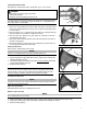
Assembly (continued) Throttle Linkage and Ignition Leads Adjust throttle trigger free play The throttle trigger free play should be approximately 4 - 6 mm (3/16” - 1/4”). Make sure that the throttle lever operates smoothly without binding. 1. Loosen the air cleaner cover knob(s) and remove the air cleaner cover. 2. Place throttle linkage (A) through adjustment fixture (B) and install wire end into large carburetor throttle swivel hole (C).
C d. Remove three screws holding shield plate (E) and plastic shield (C) to gear housing. e. Retain line head (B), adapter plate (D), shield plate, and plastic shield for conversion back to nylon line head operation. 2. Loosely attach bracket (I) to shield (J) and attach shield to bottom of gear housing (F) with hardware provided. 3. Tighten all shield hardware.
Mixing Fuel WARNING! Alternative fuels, such as E15 (15% ethanol), E-85 (85% ethanol) or any fuels not meeting Shindaiwa requirements are NOT approved for use in Shindaiwa gasoline engines. Use of alternative fuels may cause performance problems, loss of power, overheating, fuel vapor lock, and unintended machine operation, including, but not limited to, improper clutch engagement. Alternative fuels may also cause premature deterioration of fuel lines, gaskets, carburetors and other engine components.
Mixing Instructions 1. Fill an approved fuel container with half of the required amount of gasoline. 2. Add the proper amount of engine oil to gasoline. 3. Close container and shake to mix oil with gasoline. 4. Add remaining gasoline, close fuel container, and remix. IMPORTANT! Spilled fuel is a leading cause of hydrocarbon emissions. Some states may require the use of automatic fuel shutoff containers to reduce fuel spillage. Storage - Fuel storage laws vary by locality.
Starting the Engine IMPORTANT! Engine ignition is controlled by a two position switch mounted on the throttle housing labeled, “I” for ON or START and “O” for OFF or STOP. WARNING! The attachment will operate immediately when the engine starts, and could result in possible serious injury. Keep movable parts of the attachment away from objects that could become entangled or thrown, and Starting the Engine surfaces that could cause loss of control.
3. If a tachometer is available, adjust idle. Check Specifications page for correct idle speed Starting the Engine (continued) Starting the Engine (continued) ■■Squeezing the throttle lever makes the engine to warm up at idle 2 or 3 minutes before operating the unit. 1. the spark plug lead ■■Disconnect After the engine is warm, pickand upuse the plugclip wrench to remove the thespark unit and on the shoulder spark plug (turn counter clockwise to strap, if so equipped. remove). 2.
Shoulder strap WARNING! Always wear a shoulder strap or harness when operating this unit. Using a harness with a brushcutter allows you to maintain proper control of the unit and reduces fatigue during extended operation. 1. Hook the strap hook to the hanger on the outer tube. 2. Wear the shoulder strap so that the hook stays at your right hand side. 3. Adjust the length of the shoulder strap so that you can hold and operate the machine comfortably.
Using a blade WARNING! ■■Before working with a blade- equipped unit, always inspect and clean the area of objects that could interfere with or damage the blade. ■■Never use a blade near sidewalks, fence posts, buildings or other objects that could cause injury or damage. Blade Thrust “Blade thrust” is a sudden sideways or backward motion of the brushcutter. Such motion may occur when the blade jams or catches on an object such as a sapling tree or tree stump.
Maintenance General maintenancel IMPORTANT! MAINTENANCE, REPLACEMENT OR REPAIR OF EMISSION CONTROL DEVICES AND SYSTEMS MAY BE PERFORMED BY ANY REPAIR ESTABLISHMENT OR INDIVIDUAL; HOWEVER, WARRANTY REPAIRS MUST BE PERFORMED BY A DEALER OR SERVICE CENTER AUTHORIZED BY ECHO, INC. THE USE OF PARTS THAT ARE NOT EQUIVALENT IN PERFORMANCE AND DURABILITY TO AUTHORIZED PARTS MAY IMPAIR THE EFFECTIVENESS OF THE EMISSION CONTROL SYSTEM AND MAY HAVE A BEARING ON THE OUTCOME OF A WARRANTY CLAIM.
Maintenance (continued) 10-Hour maintenance (more frequently in dusty conditions) 1. Remove the air filter cover by loosening the cover screw(s) and lifting. 2. Remove and inspect the pre-filter. If the pre-filter is torn or otherwise damaged, replace it with a new one. 3. Clean the pre-filter with soap and water. Let dry before reinstalling. 4. Inspect the air filter element. If the element is damaged or distorted, replace it with a new one. 5.
Maintenance (continued) 50-hour maintenance Remove and replace the fuel filter element. ■■Use a hooked wire to extract the fuel filter from inside the fuel tank. Inspect the fuel filter element. If it shows signs of contamination, replace with a genuine Shindaiwa replacement fuel filter element. CAUTION! Make sure you do not pierce the fuel line with the end of the hooked wire. The line is delicate and can be damaged easily.
Maintenance (continued) Muffler and spark arrester maintenance If the engine becomes sluggish and low on power, check and clean the spark arrester screen. WARNING! Never operate the unit with a damaged or missing muffler or spark arrester! Operating with a missing or damaged spark arrester is a fire hazard and could also damage your hearing. Engine Cover Engine Cover Screws 1. Remove the engine cover. Muffler 2. Remove the muffler. 3. Remove the spark arrester screen and cover. 4.
Maintenance (continued) Adjusting Engine Idle The engine must return to idle speed whenever the throttle lever is released. Idle speed is adjustable, and must be set low enough to permit the engine clutch to disengage the cutting attachment. WARNING! The cutting attachment must NEVER move at engine idle! If the idle speed cannot be adjusted by the procedure described here, return the unit to your Shindaiwa dealer for inspection. Idle Speed Adjustment 1.
IMPORTANTE! When the wear indicators located at the bottom of the Speed-Feed head are worn smooth, replacement of the cover or the entire Speed-Feed head is required. Wear Indicators Wear Indicators Indicadores de desgaste Indicadores de desgaste Long Term Storage Whenever the unit will not be used for 30 days or longer, use the following procedures to prepare it for storage: ■■Clean external parts thoroughly. ■■Drain all the fuel from the fuel tank. IMPORTANT! Stored fuel ages.
Troubleshooting Guide ENGINE DOES NOT START OR HARD TO START Remedy Possible Cause What To Check Vaporlock. Valve adjustment. Engine hot/heat soaked. Let cool completely and restart. Low fuel quality. Refill with fresh, clean unleaded gasoline with a pump octane of 89 or higher mixed with an air cooled engine oil that meets or exceeds ISO-L-EGD and/or JASO FD classified oils at 50:1 gasoline/oil ratio. Valve clearance too tight. Consult with an authorized Shindaiwa servicing dealer.
Troubleshooting Guide (continued) LOW POWER OUTPUT What To Check Is the engine overheating? Engine is rough at all speeds. May also have black smoke and/or unburned fuel at the exhaust. Possible Cause Remedy Operator is overworking the unit. Use a lower throttle setting. Carburetor mixture is too lean. Consult with an authorized Shindaiwa servicing dealer. Improper fuel ratio.
Troubleshooting Guide (continued) ADDITIONAL PROBLEMS Symptom Poor acceleration. Engine stops abruptly. Possible Cause Clogged air filter. Clean the air filter. Clogged fuel filter. Replace the fuel filter. Lean fuel/air mixture. Consult with an authorized Shindaiwa servicing dealer. Idle speed set too low. Adjust idle. Check Specifications page for correct idle speed. Ignition switch turned off. Reset the switch and re-start. Fuel tank empty.
NOTES 27
NOTES 28
NOTES 29
NOTES 30
NOTES 31
Servicing Information Parts/Serial Number Genuine Shindaiwa Parts and Assemblies for your Shindaiwa products are available only from an Authorized Shindaiwa Dealer. When you do need to buy parts always have the Model Number, Type and Serial Number of the unit with you. You can find these numbers on the engine. For future reference, write them in the space provided below. Model No. _____________ SN.