Table of Contents OWNER’S AND OPERATOR’S MANUAL 1 2 3 4 Sound Proof Diesel Engine Generator 5 6 DG1000MI 7 8 9 10 11 12 13 14 Safety Guidelines Specifications 2.1 Specification Matrix 2.2 Ambient Condition Use Parts 4.1 External View 4.2 Control Panel Equipment 5.1 Monitor Display 5.2 Gauges 5.3 Fuel Line Changeover Valve Transportation and installation 6.1 Transportation 6.2 Installation Connection 7.1 Selecting Cable 7.2 Connecting Cable 7.
Introduction Thank you for purchasing Shindaiwa Sound Proof Diesel Engine Generator. z This user’s manual was created to ensure the safe operation of this equipment. Therefore, the manufacturer of this equipment strongly recommends that the user follow the instructions herein, to avoid unnecessary accidents and repairs. z Please operate this equipment after thoroughly reviewing and understanding the contents of this manual. z Please attach this manual, if the equipment will be sub-leased.
1 Safety Guidelines Danger :Suffocation from exhaust fume Exhaust fume from the engine contains many elements harmful to human. Do not operate this equipment in poorly ventilated area, such as inside a room or in a tunnel Danger :Electrical Shock Do not touch the output terminals during operation. Be sure to place covers over the output terminals and fasten with fasteners. Do not insert metal objects (such as pin or wire) into plug-in receptacles.
Caution :Injuries to eyes and skin Battery fluid contains diluted sulfuric acid. Avoid contact with eyes, skin or on clothing. If the acid comes in contact, especially with eyes, flush with a lot of water, and contact your physician immediately. Caution : Explosion Do not use the equipment or charge the battery, in the case the battery fluid level is lower than the LOWER level. Battery may emit some combustible gas, so keep it away from fire and sparks.
Caution :Injuries When lifting the equipment, always use a lift hook. Do not use Side rope-through, for it may cause equipment to drop. Always place the equipment on a flat and stable surface, to keep the equipment from sliding. When starting the engine, turn off the connected equipment and set the circuit breaker to OFF position. Do not move the equipment during operation. When performing equipment check and maintenance, always stop the engine.
■ Location of Warning labels When the warning labels become unreadable or damaged, place new labels on the appropriate location, as specified in the following figure. When ordering the label, use following part numbers.
2 Specifications 2.1 Specification Matrix Name of Generator Type Unit Rated Output Alternator Engine Operation Device Protection Device Control Panel Unit kVA kW Rated Voltage (or the below) Rated Current (or the below) Rated Voltage Rated Current Frequency Rated speed Winding Power factor Insulation class Excitation No. of poles Types Model (Manufacturer) No.
2.2 Ambient Condition Use the equipment under the following ambient condition. The other condition may cause trouble, insufficient output power or deterioration of durability. ■ Ambient Temperature : -15ºC ~ 40ºC ■ Humidity : less than 80% ■ Altitude : less than 300m 3 Use Power source for construction –use equipment, such as submersible pump Power source for lighting Power source for electric tools and home appliances 4 Parts 4.
4.2 Control panel No. 1 2 3 4 5 6 7 8 9 10 Name 3-phase circuit breaker 1-phase circuit breaker Voltage Meter Amp Meter Frequency Meter Earth Leakage Relay Panel Light & Generating Lamp Voltage Regulator Ammeter Change-Over Switch Monitor Display No.
5 Equipment 5.1 Monitor Display This generator is equipped with monitoring function for water/coolant temperature, oil pressure, battery charge, air filter flow, battery fluid level, and fuel level. When the equipment is started under normal condition, Oil Pressure and Battery Charge lamps will flash when the Starter Switch is turned from STOP to OPERATING, and all lamps will go off, immediately after the engine is started.
If the water level is normal, check for loose fan belt or possible water leak in the cooling system, after the engine is cooled down. If the water level is too low, the sensor cannot detect the water temperature. Be sure to check the water level in the radiator and the Coolant reservoir tank prior to operating the equipment. 5.1.
5.1.3 Battery Charge Monitoring Lamp (charge lamp) When the battery is not able to be charged during operation, the battery charge-monitoring lamp will flash. CHARGE In the event this occurs, stop the engine consult with the authorized distributor or our engineering section. Battery Charge Monitor cannot detect the degradation of battery life nor the battery fluid level (refer to 8-6 Checking Battery) 5.2 Gauges 5.2.
5.2.4 Fuel Gauge It shows the volume in the fuel tank. When filled up, it shows 『F』. When the hand is approaching to『E』, the volume is coming to empty. Replenish fuel enough promptly. 5.2.5 Generator Gauges 5.2.5.1 Voltage Meter Voltage Meter displays the output voltage (Phase to Phase) from the generator. Please check and confirm it showing 200V (400V) at 50Hz and 220V (440V) at 60Hz during operation. 5.2.5.2 Amp Meter Amp Meter displays the electrical (Phase) current output from the generator. 5.2.5.
5.2.6.2 Panel Light / Pilot Lamp Pilot Lamp indicates whether or not generator is generating electricity, when the engine is driving. 5.2.7 Switch 5.2.7.1 Starter Switch ①STOP When the switch is set to this position, all power will be off. The switch must be set to this position to remove the key. RUN The switch must be set to this position during operation. Do not leave the switch to this position, while the engine is stopped.A battery discharges.
5.2.7.4 Thermal Relay This relay sends the signal to the 3-Phase circuit breaker and the 1-Phase breaker to trip-off when over-current flows in the circuits. When the breaker trips-off, it is set at the middle of ON and OFF. In the case, please recover the breaker, according to the following procedure; ① Stop the engine. ② Open the control panel and push the reset button of the thermal relay. You can recover the breaker to the ON position. Do not change the preset value of the thermal relay.
5.2.8.2 Throttle Lever ①Throttle Lever The lever is to adjust the engine speed. Set it to <IDLING>when the engine starts and warms-up or cools down. When the rated power is used, set it to <RUN> (50 or 60Hz). FIXING SCREW NUT THROTTLE LEVER FREQUENCY ADJUSTING SCREW ②Frequency Adjusting Screw Set the throttle lever to <RUN>and loosen the fixing Screw nut. Turn the screw to<HIGH>to get high frequency and to<LOW>to low frequency. The equipment is set it at 50Hz and delivered.
外部燃料供給口 外部燃料戻り口(プラグ PT1/2) EXTERNAL FUEL INTAKE (PLUG : PT-1/2) EXTERNAL FUEL RETURN (PLUG : PT-1/2) 3-Way valves ) 3-Way valves (<A>position Always set the lever for 3-way valve back to A position and cover the external fuel intake and return port with the supplied plugs, after the hoses are removed. 5.3.
6 Transport and Installation 6.1 Transportation Danger :Injuries When lifting the equipment, always use a lift hook. Do not use Side rope-through to attach your lift hook, for it may cause equipment to drop. 6.1.1 Lifting Equipment Always use a Lift Hook, when lifting the equipment for transportation. LIFTING LUG 6.1.2 Transportation When transporting this equipment, make sure that the equipment is secured properly with ropes tied to the Side Rope Through.
6.2 Installation Danger :Suffocation from exhaust fume Exhaust fume from the engine contains many elements harmful to human. Do not operate this equipment in poorly ventilated area, such as inside a room or in a tunnel Caution :Suffocation from exhaust fume Do not point the exhaust fume toward pedestrians or building. Caution :Fire Always operate this equipment on flat surface and, at least 1 meter away from any objects (wall, box, etc.).
Caution :Electrical damages If the load exceeds the allowable amperage, the overheating may damage the cable. If the cable is either too long or too small a gauge, there will be greater voltage drop to loads, which may result in reduced performance in the connected loads, malfunction, or damages.
7.2 Connecting Cable Danger :Electrical Shock Before connecting or disconnecting a load cable from output terminals, always turn a circuit breaker to OFF position, stop the engine, and remove the engine key. A person performing the maintenance should always keep the key. Caution :Fire Do not connect AC output to any indoor wiring.
7.2.1.3 For 1-Phase Load(2) Terminal Voltage: 200V/220V (or 400V/440V) at 50Hz/60Hz R S T O Load Load Load 7.2.2 1-Phase Output Terminals & Receptacles The terminal Voltage: 100V/110V at 50Hz/60Hz only In the case of no use of 3-Phase output power, refer to the Following drawing and chart. U1 U0 U1-U0 W1 W0 CON3 CON1 CON4 CON2 W1-W0 Sub Total Sub Total Total Voltage (100V/110V) only U1-U0 W1-W0 CON1 5 / 5.5 5 / 5.5 1.5/1.65 CON2 1.5/1.65 - 22 - CON3 1.5/1.65 CON4 1.5/1.
7.3 Earth Leakage Relay and Grounding Danger :Electrical Shock Ground the every earth grounding terminal to the earth as set out in the manual. If even one of all is unconnected by mistake or accident, it will be much more dangerous for human body than the –relay case, because leaking current inevitably goes through the body.
In the event you cannot ground the generator to the earth, consult with the authorized distributor or our engineering section 7.3.2 Operation Check EARTH GROUNDING TERMINAL BONNET GROUNDING TERMINAL GROUNDING ROD Danger :Electrical Shock Before turning the 3-Phase circuit breaker to ON position, ensure that the breaker or the Switch of loads are positioned to OFF. Operate the 3-Phase circuit breaker, well-communicating with the electrician by the load side.
7.3.3 The earth leakage breaker relay has activated In the event the earth leakage breaker relay has activated, the earth leakage indicating lamp Turns ON and the 3-Phase earth leakage breaker (lever) trips off to be positioned in the middle between ON and OFF positions. In the above condition, even though you stop the engine once and start it again, the 3-Phase Circuit breaker (lever) does not restore to ON or OFF, and the reset button does not function, because the device keeps detecting current leakage.
8.1 Checking Engine Oil Please refer to the user’s manual for Engine separately When checking for engine oil, be sure to keep the equipment leveled, and insert the oil gauge all the way. Prior to starting the equipment, make sure to fill the engine oil to the MAX line through the oil filler. 8.1.1 OIL GAUGE Check engine oil volume IN 10-20 MINUTES LATER, OIL FILLER always after stopping engine or replenishing fuel.
8.2 Checking Coolant/water ※ Also refer to the User’s Manual for Engine Danger :Injuries Before performing any equipment check or maintenance, stop the engine, and remove the engine key. A person performing the maintenance should always keep the key. Caution :Burns Do not open the radiator cap while operating this equipment or immediately after stopping the equipment, to avoid sustaining burns from hot vapor.
Replace LLC every 2 years or 1000 hours Mixture ratio (for reference only) : Ambienr temperature -15 -20 (Celsius) Mixture ratio ℃ ℃ 30% 35% ℃ -30 45% 8.2.3 Coolant Capacity ( Unit: L) Total Coolant Volume ( including reservoir tank) 22.8 (1.5) The value of ( ) shows the reservoir tank`s volume. 8.3 Checking Fan Belt ※Also refer to the user’s manual for Engine separately Danger :Injuries Before performing any equipment check or maintenance, stop the engine, and remove the engine key.
8.3.2 Condition Check for any damage on the fan belt. Replace if necessary. Refer to the User’s manual for Engine for adjusting and replacing of the fan belt. 8.4 Checking Fuel Caution :Fire Always wipe any drip of Diesel fuel or oil. Do not use this equipment when a leak is found. Repair the equipment before use. Check for the fuel level in the tank. Add if necessary. Use Diesel fuel, ASTM D975 No.2-D in the event ambient temperature reaches down to –5℃.
Notice: Do not use home heating oil or gasoline in your diesel engine; either may cause engine damage. 8.5 Checking Fuel, Engine Oil, and Water leakage Caution :Fire Do not use this equipment when a leak is found. Repair the equipment before use. Be sure to check for any fuel leak at the hose connection, and oil and coolant leak by opening side doors. 8.6 Checking Battery Caution :Injuries to eyes and skin Battery fluid contains diluted sulfuric acid. Avoid contact with eyes, skin or on clothing.
Replacing the battery Two batteries are connected in series order. Whenever you replace battery or disconnect cables, always proceed with the following steps, otherwise battery may short-circuit. 8.6.
9 Operation 9.1 Initializing / preparation :Suffocation from exhaust fume Exhaust fume from the engine contains many elements harmful to human. Do not operate this equipment in poorly ventilated area, such as inside a room or in a tunnel Caution Do not point the exhaust fume toward pedestrians or building. Caution ① ② ③ :Fire Temperature around muffler and exhaust can get extremely high. Keep any inflammable items (such as fuel, gas, paint, etc.) away from the equipment.
Do not drive the starter motor for more than 10 seconds successively If you need to restart, wait at least 30 seconds before the retry. ④ ⑤ ⑥ Release the starter switch, as soon as the engine is started Keep the engine idle for at least 5 minutes Set the throttle lever to RUN. Ensure that the frequency meter shows the following frequency at no load. No-load frequency(Revolution) 50Hz Operation 52.5Hz(1575min-1) 60Hz Operation 63.
9.2 200/400 Voltage Changeover - Dual Voltage System The generator is incorporated with dual voltage system. So, you can easily change 400/440V to 200/220V or adversely. You can get 200V or 400V by changing the combination of output terminals with bus plates Danger :Electrical Shock Be sure to set the circuit breaker OFF and stop operation before setting. Caution : Damages to the property ① ② Be sure to set the bus plates at the right positions and screw them securely.
3-PHASE 400/440V TERMINALS BUS PLATES 2 PLATES OVERLAPPED ③ The 3-phase voltage is energized to the 3-phase output terminals. Refer to 7-2. Connecting cable ④ Starting the engine and turning the 3-phase breaker to ON, the 3-phase current is sent to the 3-phase output terminals. 9.3 During Operation 9.3.1 Post startup check Make sure that all meters (gauges) and displays are working properly (refer to 5.
Caution ① ② :Fire Always wipe any drip of gasoline or oil. Add fuel to the fuel tank Turn the starter switch to position. It will take approximately 30 seconds to vacuum the air out. Ensure that all the air is completely extracted from fuel line, by setting the throttle lever to IDLING and start the engine. In the case air is in the fuel line, the engine speeds is unstable, and proceed with the vacuuming steps again. 9.
9.6 Connecting to External Fuel Tank Caution :Fire Always stop the engine, when working on the fuel line. Always wipe any drip of Diesel fuel or oil. Do not use this equipment when a leak is found. Repair the equipment before use. Ensure that there is no fuel leakage on the fuel line after the fuel line working finished.
10 Maintenance Danger :Electrical Shock ● Injuries Before performing any equipment check or maintenance, stop the engine, and remove the engine key. A person performing the maintenance should always keep the key. Caution :Fire ● Burns When checking engine, always stop the engine, and keep away from fire. Wait until the engine cools down, before performing any checks. Caution :Fire Always wipe any drip of gasoline or oil. Do not use this equipment when a leak is found.
Startup check Description Every 200hrs Every 400hrs Every 500hrs Every 1000hrs Engine Side Clean each parts / tightening Engine oil checks / add oil Engine oil change (1st time at 50 hr mark) Oil Filter change (1st time at 50 hr mark) Coolant level check / add coolant Exhaust color check Coolant change ◯ ◯ ◯ ◯ ◯ ◯ ◯ ◯ ◯ or 2 yr.
10.1 Oil Change ① ② First time From second time 50 hour mark Every 200 hours Remove Oil Filler cap OIL FILLER OIL FILLER CAP Loosen the engine oil drain plug and allow the oil to ③ ④ drain fully ⑤ You should check the oil level on the oil gauge Reinstall the drain plug Add oil from oil filler and fill up to the MAX level. OIL GAUGE Reinstall the filler cap hand-tight For the types of engine oil to use and volume to replace, refer to 8-1 Checking Engine Oil OIL DRAIN PLUG 10.
10.
10.4 Draining Water from Water Separator When a float (red) is at drain level, drain water. ① ② Loosen the drain plug and drain water. Screw the drain plug, when finishing drain. After draining finishes, extract the air in fuel line. (Refer to 9-3 During operation.) 10.
10.6 Clean gauze filter in water separator AIR EXTRACTION PLUG RING NUT Clean ① Every 500 hours GAUZE FILTER Loosen the lever and then loosen the air ② extraction plug. Turn the ring nut counter-clockwise to remove the cup and the gauze filter after the ③ fuel inside does not come out from the lever. Wash the gauze filter in Diesel fuel and reinstall the unit in the reverse order. Tightening Torque Ring Nut 15Nm{1.5kgfm} Air Extraction Plug 10Nm{1.
GAUZE FILTER Put a tray under the lever in order to catch spilled fuel when loosing the lever. Gaskets are attached to both ends of joint pipe. Be careful not to lose and EYEBOLTS install them in the unit without fail. Change both gauze filter and eyebolt when gauze filter is damaged. Extract the air in fuel line after gauze filter washing finishes. (Refer to 9-3. During operation.) Ensure that there is no fuel leakage after reinstallation. Eyebolt Part No.
10.9 Draining Water from Fuel Tank Drain water ① ② Every 200 hours Unscrew the Fuel drain plug Reinstall the drain plug, after draining water fully FUEL DRAIN PLUG 10.
11 long-term Storage Danger :Electrical Shock ● Injuries Before performing any equipment check or maintenance, stop the engine, and remove the engine key. A person performing the maintenance should always keep the key. Caution :Fire ● Burns Temperature around muffler and exhaust can get extremely high. Keep any inflammable items (such as fuel, gas, paint, etc.) away from the equipment. When checking engine, always stop the engine, and keep away from fire.
11.2 Stacking Danger :Injuries If you have to stack two generators in warehouse, always proceed with the following steps. Ensure that there is no dent on bonnet, loosing bolt or no bolt in the generators. Always place the generators on a flat and stable surface, to keep the equipment from sliding, And to be endurable for the total weight. When lifting the equipment, always use a lift hook.
12 Troubleshooting Danger :Electrical Shock Do not operate the equipment, if the equipment or you are wet. Before performing any equipment check or maintenance, stop the engine. Caution :Injuries When performing equipment check and maintenance, always stop the engine. Caution :Fire ● Burns Battery may emit some combustible gas, so keep it away from fire and sparks. Temperature around muffler and exhaust can get extremely high. Keep any inflammable items (such as fuel, gas, paint, etc.
Engine does not start Symptom Presumable Cause Action Starter motor does not 1. Battery output is weak 1. Check/ battery liquid/ or Charge drive or speed is low. 2. 3. Battery is deteriorated Battery terminal is OFF or loose 2. 3. Change battery Fix/Tighten terminal 4. Battery terminal is corroded 4. Clean terminal 5. 6. Starter switch or relay is defective 5. Starter motor is defective 6. Ask our distributor to repair Ask our distributor to repair Starter motor drives but 1.
Overheated 1. 2. Engine thermostat is defective Water temp sensor is defective 1. 2. Ask our distributor to repair Ask our distributor to repair 3. Water temp meter is defective 3. Ask our distributor to repair 4. 5. Fan belt tension is weak Coolant is insufficient 4. 5. Check/Adjust fan belt Check/Supply coolant 6. Radiator core is clogged 6. Clean radiator core Black smoke comes out from 1. Air filter element is clogged muffler 1. Check/Change air filter element 2.
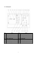
13 Generator Wiring Diagram - 51 -
14 Engine Wiring Diagram - 52 -