SHINDAIWA OWNER’S/OPERATOR’S MANUAL EB254 BLOWER Minimize the risk of injury to yourself and others! Read this manual and familiarize yourself with the contents. Always wear eye and hearing WARNING! protection when operating this unit.
Introduction The Shindaiwa EB254 has been designed and built to deliver superior performance and reliability without compromise to quality, comfort, safety, or durability. The information contained in this manual describes units available at the time of production. While every attempt has been made to give you the very latest information about your Shindaiwa EB254 blower, there may be some differences between your EB254 blower and what is described here.
General Safety Instructions Work Safely Blowers operate at a very high speed and can do serious damage or injury if they are misused or abused. Never allow a person without training or instruction to operate your EB254 Blower! Stay Alert You must be physically and mentally fit to operate this unit safely. WARNING! Never make unauthorized modifications or attachment installations. Never use attachments not approved by Shindaiwa for use on this unit.
The Properly Equipped Operator Always wear eye protection such as a face shield or goggles while operating this unit. Never operate the blower when visibility is poor. Wear hearing protection when operating this unit. Wear a dust mask to reduce the risk of inhalation injuries. Wear close-fitting clothing to protect legs and arms. Gloves offer added protection and are strongly recommended. Do not wear clothing or jewelry that could get caught in machinery or underbrush.
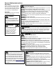
Unit Description Handle Ignition Switch Throttle Limiter Lever Throttle Lever Recoil/ Starter Air Cleaner Cover Fuel Primer Bulb Blower Tube Nozzle Exhaust Fuel Filler Cap IMPORTANT! dB(A) 68 Category II Figure 3 Measured at 50 ft. (15m) per ANSI B175.2 Contents Before assembling the blower, make sure you have all required components. • Power unit and blower assembly.
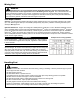
Specifications Model EB254 Engine Type 4-cycle air cooled gasoline engine, vertical cylinder Engine Bore x Stroke 34 mm x 27 mm (1.3 in x 1.1 in.) Engine Displacement 24.5cc (1.5 in3) Unit Weight (without blower tube) Less Fuel Unit Dimensions (LxWxH) 4.9 kg (10.8 lb) 897 x 255 x 375 mm (35 x 10 x 15 in) Fuel Tank Capacity 0.6 liter/20.4 oz.
Assembling the Blower WARNING! Danger from rotating impeller! Stop the engine before installing or removing the blower tubes! Never perform any maintenance or assembly procedures on this unit while the engine is running! Push the blower tube over the discharge port and locking pin Place the blower upright on the ground or on a sturdy work surface. 1. Grasp the blower tube as shown, and push the tube over the blower discharge port and locking pins. Locking Pin Blower 1 Tube Rotate clockwise to lock 2.
Mixing Fuel WARNING! Alternative fuels, such as E15 (15% ethanol), E-85 (85% ethanol) or any fuels not meeting Shindaiwa requirements are NOT approved for use in Shindaiwa gasoline engines. Use of alternative fuels may cause performance problems, loss of power, overheating, fuel vapor lock, and unintended machine operation, including, but not limited to, improper clutch engagement. Alternative fuels may also cause premature deterioration of fuel lines, gaskets, carburetors and other engine components.
Mixing Instructions 1. Fill an approved fuel container with half of the required amount of gasoline. 2. Add the proper amount of engine oil to gasoline. 3. Close container and shake to mix oil with gasoline. 4. Add remaining gasoline, close fuel container, and remix. IMPORTANT! Spilled fuel is a leading cause of hydrocarbon emissions. Some states may require the use of automatic fuel shut-off containers to reduce fuel spillage. After use • DO NOT store a unit with fuel in its tank. Leaks can occur.
Starting the Engine (continued) Starting Procedure 1. Place the blower on the ground. 2. Prime the fuel system by repeatedly depressing the fuel primer bulb until no air bubbles are visible in the fuel discharge line. IMPORTANT! The primer system only pushes fuel through the carburetor. Repeatedly pressing the primer bulb will not flood the engine with fuel. 3. Cold Engine Only. Choke the engine by moving the choke lever up (choke is closed). See Figure 5. Choke Open Choke Closed Figure 5 4.
Stopping The Engine 1. Cool the engine by allowing it to run at idle for 2–3 minutes. 2. Slide the ignition switch towards the rear to “O” (OFF). See Figure 8. Ignition Switch OFF Throttle Lever Figure 8 Operating Blower WARNING! Always wear safety glasses, hearing protection and a face filter mask or serious personal injury may result. Do not point the blower pipe in the direction of people or pets.
Throttle Control The EB254 is equipped with a multi-function throttle control. The “Cruise” function allows the operator to use a thumb controlled lever for constant speed use without using the throttle trigger. This is useful for limiting the fatigue caused from holding the throttle for extended periods of time. On the opposite side, a two position “Limiter” control allows full engine speed when set for “Turbo” or limits the throttle to a pre-set engine speed when set to low noise (dB) setting.
Maintenance IMPORTANT! Maintenance, replacement or repair of emission control devices and systems may be performed by any repair establishment or individual, However, warranty repairs must be performed by a dealer or service center authorized by Echo, Inc. The use of parts that are not equivalent in performance and durability to authorized parts may impair the effectiveness of the emission control system and may have a bearing on the outcome of a warranty claim.
Air Filter 1. Remove the air cleaner cover by loosening the thumb screw and lifting up. See Figure 13A. Figure 13A Unscrew Fasteners 2. Remove and inspect the pre-filter. If the pre-filter is torn or otherwise damaged, replace it with a new one. See Figure 13B. 3. Clean the pre-filter with soap and water. Let dry before reinstalling. 4. Inspect the air cleaner element. If the element is damaged or distorted, replace it with a new one. See Figure 13B. 5.
Spark Plug CAUTION! Never allow dirt or debris to enter the cylinder bore! Before removing the spark plug, thoroughly clean the spark plug and cylinder head area! Allow the engine to cool before servicing the spark plug! Cylinder threads can be damaged by tightening or loosening the spark plug while the engine is hot! 1. Use the spark plug wrench to remove the spark plug. See Figure 14. 2. Clean and adjust the spark plug gap to 0.6mm (0.024 in.).
Valve Adjustment ■■Combustion chamber should be decarbonized, and the valve clearance should be adjusted. It is highly recommended that this is done by a Shindaiwa-trained service technician. IMPORTANT! The valve clearance should be adjusted. It is highly recommended that this is done by a Shindaiwa-trained service technician. CAUTION! • Performing a valve adjustment incorrectly may cause hard starting and/or can damage the unit.
Exhaust System Spark Arrester Maintenance WARNING! Never operate this blower with a damaged or missing muffler or spark arrester! Operating with missing or damaged exhaust components is a fire hazard, and can also damage your hearing! Hard starting or a gradual loss of performance can be caused by carbon deposits lodged in the spark arrester screen. For maximum performance, the spark arrester screen should be periodically cleaned as follows. See Figure 16.
Idle Adjustment Before adjustment make sure that: • Air filter is clean and properly installed. • Spark arrestor screen is free of carbon. • Blower pipes are installed. Idle Ajustment Screw 1. Start engine, run at idle for 2-3 minutes. 2. Check idle speed and reset if necessary. If a tachometer is available, idle speed screw should be set to the specifications found on Page 6 “Specifications” of this manual. Turn idle screw clockwise to increase idle speed; counter clockwise to decrease idle speed.
Troubleshooting Guide ENGINE DOES NOT START OR HARD TO START Possible Cause What To Check Vaporlock. Valve adjustment. Remedy Engine hot/heat soaked. Let cool completely and restart. Low fuel quality. Refill with fresh, clean unleaded gasoline with a pump octane of 89 or higher mixed with an air cooled engine oil that meets or exceeds ISO-L-EGD and/or JASO FD classified oils at 50:1 gasoline/oil ratio. Valve clearance too tight. Consult with an authorized Shindaiwa servicing dealer. Adjust valves.
Troubleshooting Guide (continued) LOW POWER OUTPUT What To Check Is the engine overheating? Engine is rough at all speeds. May also have black smoke and/or unburned fuel at the exhaust. Possible Cause Operator is overworking the unit. Use a lower throttle setting. Carburetor mixture is too lean. Consult with an authorized Shindaiwa servicing dealer. Improper fuel ratio.
Troubleshooting Guide (continued) ADDITIONAL PROBLEMS Symptom Poor acceleration. Engine stops abruptly. Possible Cause Clogged air filter. Clean the air filter. Clogged fuel filter. Replace the fuel filter. Lean fuel/air mixture. Consult with an authorized Shindaiwa servicing dealer. Idle speed set too low. Adjust idle. Check Specifications page for correct idle speed. Ignition switch turned off. Reset the switch and re-start. Fuel tank empty.
SHINDAIWA LIMITED WARRANTY STATEMENT FOR PRODUCT SOLD IN USA AND CANADA BEGINNING 01/01/2010 ECHO, INC’S RESPONSIBILITY ECHO Incorporated’s (ECHO, INC.) Limited Warranty, provides to the original purchaser that this Shindaiwa product is free from defects in material and workmanship. Under normal use and maintenance from date of purchase, ECHO, INC.
PURCHASED REPAIR PARTS AND ACCESSORIES • 90-day all applications ATTENTION ENGINE POWERED PRODUCT OWNERS This Shindaiwa engine powered product is a quality-engineered unit which has been manufactured to exact tolerances to provide superior performance. To help ensure the performance of the unit, it is required to use engine oil which meets the ISO-L-EGD Standard per ISO/CD 13738 and JASO M345/FD Standards.
ECHO INCORPORATED EMISSION CONTROL WARRANTY STATEMENT FOR ECHO AND SHINDAIWA BRANDS The Environmental Protection Agency (EPA) and the California Air Resources Board (C.A.R.B.) and ECHO Incorporated (ECHO Inc.) are pleased to explain the emission control system warranty on your 2010 and later equipment/small off-road engine (SORE). New equipment/SORE must be designed, built and equipped to meet stringent EPA and C.A.R.B. anti-smog standards. ECHO Inc.
NOTES 25
NOTES 26
NOTES 27
Servicing Information Parts/Serial Number Genuine Shindaiwa Parts and Assemblies for your Shindaiwa products are available only from an Authorized Shindaiwa Dealer. When you do need to buy parts always have the Model Number, Type and Serial Number of the unit with you. You can find these numbers on the engine. For future reference, write them in the space provided below. Model No. _____________SN.