SHINDAIWA OWNER’S/OPERATOR’S MANUAL LE2510 LAWN EDGER LE2510 WARNING! Minimize the risk of injury to yourself and others! Read this manual and familiarize yourself with the contents. Always wear eye and hearing protection when operating this unit. Part Number 81719 Rev.
Introduction Attention Statements The Shindaiwa 2510 Series hand held power equipment has been designed and built to deliver superior performance and reliability without compromise to quality, comfort, safety or durability. Throughout this manual are special “Attention Statements”. Shindaiwa engines represent the leading edge of high-performance engine technology, delivering exceptionally high power with remarkably low displacement and weight.
Safety Instructions Work Safely Shindaiwa Edgers operate at very high speeds and can do serious damage or injury if they are misused or abused. Never allow a person without training or instruction to operate this unit! WARNING! Never make unauthorized attachment installations. Do not use attachments not approved by Shindaiwa for use on this unit. Stay Alert You must be physically and mentally fit to operate this unit safely.
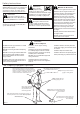
Be Aware of the Working Environment Avoid long-term operation in very hot or very cold weather. Make sure bystanders or observers outside the 50-foot “danger zone” wear eye protection. Always make sure the appropriate cutting attachment shield is correctly installed. 50 FEET Be extremely careful of slippery terrain, especially during rainy weather. Reduce the risk of bystanders being struck by flying debris.
Product Description Using the accompanying illustrations as a guide, familiarize yourself with this unit and its various components. See Figure 4. Understanding your unit helps ensure top performance, long service life, and safer operation. LE2510 LAWN EDGER Ignition Switch Grip Handle Cutting Attachment Shield WARNING! Throttle Interlock Outer Tube Do not make unauthorized modifications or alterations to any of these units or their components.
Assembly and Adjustments Install Gearcase Assembly 1. Loosen gearcase clamp screw. 2. Remove the gearcase index screw. 3. Slide the gearcase oriented as shown in Figure 5 onto the shaft tube insuring that the flex drive is engaged in the gearcase. NOTE: It may be necessary to pull the flex cable out from the shaft tube, engage into the gearcase and then slide the assembly onto the shaft tube. 4. Reinstall the index screw and tighten securely. 5. Tighten the clamp screw and torque to 52 – 69 inch pounds.
Mixing Fuel CAUTION! CAUTION! Examples of 50:1 mixing quantities Some types of gasoline contain alcohol as an oxygenate. Oxygenated gasoline may cause increased operating temperatures. Under certain conditions, alcohol-based gasoline may also reduce the lubricating qualities of some 2-cycle mixing oils.
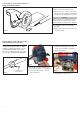
Starting the Engine IMPORTANT!! Engine ignition is controlled by a two position switch mounted on the throttle housing labeled, “I” for ON or START and “O” for OFF or STOP. ON Make sure the cutting attatchment is clear of obstructions! Throttle Lock Button Figure 9 1. Slide the ignition switch to the “ON” position. See Figure 9. 2. Set the throttle lever to the “fast idle”; Figure 12 a. Squeeze the throttle lever toward the 5. While holding the outer tube firmly handgrip on the shaft tube.
Stopping the Engine Idle the engine briefly before stopping (about 2 minutes), then slide the ignition switch to the “O” (Engine OFF) position. OFF Figure 14 Adjusting Engine Idle The engine must return to idle speed whenever the throttle lever is released. Idle speed is adjustable, and must be set low enough to permit the engine clutch to disengage the cutting attachment.
Using a Hand-held Edger Guidelines for Operating the Edger Before edging, make sure the area is soft enough so the blade does not bog down. If necessary, water the area before edging. Remove debris and other obstacles that could be thrown by the rotating blade. WARNING! Plan your work so the edger blade is always on your right-hand side.
General Maintenance IMPORTANT! MAINTENANCE, REPLACEMENT OR REPAIR OF EMISSION CONTROL DEVICES AND SYSTEMS MAY BE PERFORMED BY ANY REPAIR ESTABLISHMENT OR INDIVIDUAL; HOWEVER, WARRANTY REPAIRS MUST BE PERFORMED BY A DEALER OR SERVICE CENTER AUTHORIZED BY SHINDAIWA CORPORATION THE USE OF PARTS THAT ARE NOT EQUIVALENT IN PERFORMANCE AND DURABILITY TO AUTHORIZED PARTS MAY IMPAIR THE EFFECTIVENESS OF THE EMISSION CONTROL SYSTEM AND MAY HAVE A BEARING ON THE OUTCOME OF A WARRANTY CLAIM.
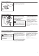
10/15-Hour Maintenance Every 10 to 15 hours of operation: 0.024–0.028 inch (0.6–0.7 mm) n Remove and clean the spark plug. Adjust the spark plug electrode gap to 0.024 0.028 inch (0.6-0.7 mm). If the spark plug must be replaced, use only an NGK CMR5H or equivalent resistor type spark plug of the correct heat range. See Figure 19. Clean the spark plug and check the gap at the electrode. NOTE: The NGK CMR5H also meets the requirements for electro magnetic compliance (EMC).
50-Hour Maintenance (continued) CAUTION! The D-shaped shim washer must be positioned with its flat edge toward the shaft tube. Gearcase Shaft Tube D-shaped Shim Washer Flat (toward26024 tube) Figure 23 Inspect the Gearcase Protector The metal gearcase protector (p/n 7295816210) is installed to protect the gearcase flange from damage when working close to sidewalks or other abrasive surfaces, and should be routinely inspected for damage or excessive wear.
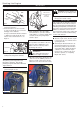
Spark Arrester Screen Maintenance If the engine becomes sluggish and low on power, check and clean the spark arrester screen. Cover Engine Cover Screws WARNING! Never operate this unit with a damaged or missing muffler or spark arrester! Operating with missing or damaged exhaust components is a fire hazard, and can also damage your hearing! Muffler Muffler Gasket 1. With a 3 mm hex wrench remove the 4 engine cover screws and the engine cover. See Figure 25. Spark Arrester Cover 2.
Troubleshooting Guide ENGINE DOES NOT START What To Check iÃÊÌ iÊi}iÊVÀ>¶ Possible Cause Remedy NO Faulty recoil starter. Fluid in the crankcase. Internal damage. Consult with an authorized servicing dealer. NO Loose spark plug. Excess wear on cylinder, piston, rings. Valves not seating. Tighten and re-test. Fuel incorrect, stale or contaminated; mixture incorrect.
Troubleshooting Guide (continued) ADDITIONAL PROBLEMS Symptom Poor acceleration. Engine stops abruptly. Engine difficult to shut off. Top of engine is getting dirty and oily. Cutting attachment rotates at engine idle. Engine will not idle down. Possible Cause Remedy Clogged air filter. Clean the air filter. Clogged fuel filter. Replace the fuel filter. Lean fuel/air mixture. Consult with an authorized servicing dealer. Idle speed set too low. Adjust: 3,000 (±300) RPM (min-1).
The following statement only applies to United States and its territories Shindaiwa Corporation Federal Emission Design And Defect Limited Warranty Utility And Lawn And Garden Engines Shindaiwa Corporation warrants to the initial purchaser and each subsequent owner, that this utility equipment engine (herein engine) is designed, built and equipped to conform at the time of initial sale, to all applicable regulations of the U.S.
NOTES Shindaiwa Inc. 11975 S.W. Herman Rd. Tualatin, Oregon 97062 USA Telephone: 503 692-3070 Fax: 503 692-6696 www.shindaiwa.com 18 Shindaiwa Corporation Head Office: 6-2-11, Ozuka-Nishi Asaminami-Ku, Hiroshima 731-3167, Japan Telephone: 81-82-849-2220 Fax: 81-82-849-2481 ©2007 Shindaiwa, Inc. Part Number 81719 Revision 2/07 Shindaiwa is a registered trademark of Shindaiwa, Inc. Specifications subject to change without notice.
NOTAS Shindaiwa Inc. 11975 S.W. Herman Rd. Tualatin, Oregon 97062 USA Teléfono: 503 692-3070 Fax: 503 692-6696 www.shindaiwa.com Shindaiwa Corporation Head Office: 6-2-11, Ozuka-Nishi Asaminami-Ku, Hiroshima 731-3167, Japan Teléfono: 81-82-849-2220 Fax: 81-82-849-2481 ©2007 Shindaiwa, Inc. Despida el Número 81719 Revisión 2/07 Shindaiwa es una marca registrada de Shindaiwa, Inc. Especificaciones sujetas a cambio sin previo aviso.
Shindaiwa Corporation Garantía limitada de defectos y diseño de emisiones federales Motores de uso general y para parques y jardines Shindaiwa Corporation garantiza al comprador inicial y a cada propietario siguiente, que este motor para equipos de uso general (de aquí en adelante motor) está diseñado, fabricado y equipado para cumplir, en el momento de la venta inicial, con todas los reglamentos vigentes de la Administración de Protección Ambiental de EE.UU.
Guia Diagnostico (continuación) Sintoma Aceleración deficiente. El motor se apaga abruptamente. Se hace difícil apagar el motor. La parte superior del motor se está ensuciando y engrasando. El accesorio de corte gira con el motor en marcha mínima. El motor no baja a marcha mínima. PROBLEMAS ADICIONALES Posible Causa Filtro de aire obstruído. Remedio Limpie el elemento del filtro de aire. Consulte con su agente de servicio autorizado. La mezcla de combustible/aire es muy pobre.
Guia Diagnostico Que Revisar ¿Arranca el motor? NO El Motor No Arranca Posible Causa Arrancador defectuoso. Liquido en el cárter. Daños internos. Remedio Consulte con su agente de servicio autorizado. SI ¿Buena compresión? NO Bujía floja. Desgaste en el cilindro, pistón, anillos. Las válvulas no están asentadas. Ajuste y pruebe otra vez. Consulte con su agente de servicio autorizado.
Mantenimiento de la Maya Guardachispas Si el motor se pone peresoso o tiene baja potencia, revise y limpie la maya del guardachispas. ¡ADVERTENCIA! Tornillos de la tapa del motor Tapa Nunca opere esta unidad con un silenciador o un guardachispas dañado o faltante. De lo contrario, la operación puede constituir un riesgo de incendio y podría también lesionar sus oídos. 1. Con una llave hexagonal de 3 mm retire los cuatro tornillos de la tapa del motor y la tapa del motor. Consulte la figura 25.
Mantenimiento Cada 50 Horas (continuación) PRECAUCIÓN! La arandela de calce de en forma de D se debe posicionar con su orilla plana hacia el tubo del eje.
Mantenimiento Cada 10/15 Horas Limpie la bujía y revise la distancia del electrodo. 0.024 – 0.028 pulgadas (0.6 - 0.7 mm) Cada 10 ó 15 horas de operación: n Retire y limpie la bujía. Ajuste la distancia del electrodo a 0.024-0.028 pulgadas (0.6 -0.7 mm). Si la bujía necesita ser reemplazada, use solamente una bujía NGK CMR5H o una bujía equivalente con resistencia al calor correcta. Consulte la figura 19. NOTA La NGK CMR5H tambíen cumple con los requisitos de la regulación de electro mangnéticos (EMC).
Mantenimiento General IMPORTANTE! EL MANTENIMIENTO, REEMPLAZO O REPARACION DE LOS SISTEMAS Y DISPOSITIVOS DE CONTROL DE EMISION PUEDEN SER EFECTUADOS POR CUALQUIER ESTABLECIMIENTO O INDIVIDUO; SIN EMBARGO, LAS REPARACIONES DE GARANTIA DEBEN SER EFECTUADAS POR SU CENTRO DE SERVICIO O DISTRIBUIDOR AUTORIZADO POR SHINDAIWA CORPORATION EL USO DE PARTES QUE NO SON EQUIVALENTES EN RENDIMIENTO Y DURABILIDAD A LAS PARTES AUTORIZADAS PUEDEN AFECTAR LA EFECTIVIDAD DE SU SISTEMA DE CONTROL DE EMISION Y PUEDE INFLUENC
Utilizando el Orillador de Mano Las pautas para Operar la orilladora Antes bordear, asegurase que el área este suave porque la cuchilla podría atascarse. Si necesario, riegue el área antes de bordear. Quite escombros y otros obstáculos que podrían ser tirados por la cuchilla al girar. Planee su trabajo de tal manera la hoja de orilladora es siempre en su lado derecho. Empiece cada pasada posicionando la unidad sobre el trabajo y con el motor a media marcha.
Parada del Motor Apagado Ponga el motor en marcha mínima por dos o tres minutos antes de apagarlo, luego deslice el interruptor de ignición a la posición “O” (motor apagado). Figura 14 Ajuste de Marcha Mínima del Motor El motor debe retornar a marcha mínima cuando la palanca del acelerador es liberada. La marcha mínima es ajustable y debe ser suficientemente mínima para Figura 15 Tornillo de marcha mínima 1.
Arranque del Motor IMPORTANTE! El encendido del motor está controlado por un interruptor de dos posiciones montado en el mango del acelerador indicado “I” (encendido o arranque) y “O” (apagado o pare). Encendido 4. Posicione la palanca del cebador en la posición CLOSED (cerrado) si el motor está frío. 6. Cuando arranque el motor, mueva despacio la palanca del cebador a la posición “OPEN” (abierto). Consulte la figura 16.
Mezcla de Combustible Este motor está diseñado solamente para funcionar con una mezcla de 50:1 de gasolina sin plomo y aceite de mezclar para motores de 2 tiempos. ISO-L-EGD o JASO FC. El uso de aceites de mezclar no autorizados puede conducir a excesos de depósitos de carbón. Algunas gasolinas contienen alcohol como un oxigenante. Combustibles oxigenados pueden aumentar la temperatura del motor durante su funcionamiento.
Ensamblaje y Ajustes Instalación de la Caja de Engranaje 1. Afloje el tornillo de abrazadera de la caja de engranaje. 2. Quite el tornillo del índice de la caja de engranaje. 3. Deslice el caja de engranajes como se muestra en la Figura 5 asegurándose que el eje de impulsión este conectado con la caja de engranaje. NOTE: Puede que sea necesario sacar el cable flexible del tubo de eje, conéctelo con la caja de engranaje y después deslice el ensamblaje en el tubo del eje. Figura 5 4.
Descripción del Producto Use las ilustraciones como guía, familiarícese con esta unidad y sus varios componentes. Consulte la figura 4. Conociendo la unidad le ayudará a obtener alto rendimiento, vida útil más prolongada y operación con seguridad. ¡ADVERTENCIA! No haga modificaciones o alteraciones no autorizadas a ninguna de éstas máquinas ni a sus componentes.
Esté Alerta del Area de Trabajo Evite trabajar durante largo tiempo bajo temperaturas muy calientes o muy frías. Tenga mucho cuidado al trabajar sobre terrenos resbalosos, especialmente en tiempo de lluvia. 50 píes. Cerciórese de que los transeúntes u observadores estén fuera de la “zona de peligro” de 50 píes usen protección de ojos. Reduzca el riesgo de que algún transeúnte sea golpeado por un objeto volante.
Instrucciones Generales de Seguridad Trabaje con cuidado Podadoras Shindaiwa operan a velocidades altas y pueden causar daños o lesiones serias si son mal usadas o abusadas. Nunca permita que una persona sin entrenamiento o instrucción opere esta unidad! ¡ADVERTENCIA! Nunca instale accesorios no autorizados. No use accesorios no aprobados por Shindaiwa en esta unidad. Mantengase alerta Usted debe estar en optimas condiciones física y mental para operar esta maquina en forma segura.
A travéz de este manual se encuentran “declaraciones de seguridad” especiales. La desmalezadora Shindaiwa Serie 2510 ha sido diseñada y construida para suministrar un rendimiento superior sin comprometer calidad, comodidad ni durabilidad. Declaraciones de Seguridad Introducción Los motores Shindaiwa representan la tecnología líder de motores de alto rendimiento, de poco peso y pequeña cilindrada con excepcional alta potencia.
MANUAL DEL PROPIETARIO/OPERADOR SHINDAIWA ORILLADORA DE GRAMA LE2510 LE2510 ¡ADVERTENCIA! Disminuya el riesgo de sufrir lesiones o causar lesiones a otros! Lea este manual y familiaricese con su contenido. Siempre use protección para los ojos y oídos cuando opere esta máquina. Número de pieza 81719 Rev.