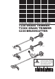
ENGLISH SHINDAIWA OWNER’S/OPERATOR’S MANUAL T230 GRASS TRIMMER T230X GRASS TRIMMER C230 BRUSHCUTTER T230 T230X C230 WARNING! Minimize the risk of injury to yourself and others! Read this manual and familiarize yourself with the contents. Always wear eye and hearing protection when operating this unit. ® Part Number 62064-94013 Rev.
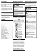
Introduction Attention Statements General Safety Instructions Shindaiwa 230-series hand held power equipment has been designed and built to deliver superior performance and reliability without compromise to quality, comfort, safety or durability. Throughout this manual are special “Attention Statements.” Work Safely Shindaiwa’s high-performance engines represent the leading edge of 2-cycle engine technology, delivering exceptionally high power with remarkably low displacement and weight.
General Safety Instructions The Properly Equipped Operator Stay Alert You must be physically and mentally fit to operate this unit safely. WARNING! Never operate power equipment of any kind if you are tired or if you are under the influence of alcohol, drugs, medication or any other substance that could affect your ability or judgement. Wear hearing protection devices and a broad-brimmed hat or helmet. Wear close-fitting clothing to protect legs and arms.
Safety Labels IMPORTANT! Safety and Operation Information Labels: Make sure all information labels are undamaged and readable. Immediately replace damaged or missing information labels. New labels are available from your local authorized Shindaiwa dealer. READ THE OPERATOR’S MANUAL WEAR HEARING AND ANSI Z87.1 APPROVED EYE PROTECTION 50 FEET (15m) KEEP BYSTANDERS AWAY AT LEAST 50 FEET (15m) T230 BEWARE OF THROWN OR RICOCHETED OBJECTS DO NOT OPERATE THIS MACHINE WITH A BLADE Shindaiwa Inc.
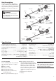
Unit Description Using the accompanying illustrations as a guide, familiarize yourself with this unit and its various components. Understanding the product helps ensure top performance, long service life, and safer operation. See Figure 4. Ignition Switch Fuel Tank Outer Tube Throttle Trigger Gearcase WARNING! Tank T230 Protector GRASS TRIMMER Handle (for trimmer use only) Do not make unauthorized modifica tions or alterations to any of these units or their components.
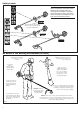
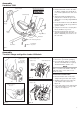
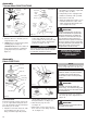
Assembly Driveshaft/Powerhead All Models Connect the Outer Tube to the Powerhead. 1. Place the powerhead on a clean, flat surface, spark plug facing up. See Figure 6. 2. Use the 4 mm hex wrench to loosen the tube clamp screw. Tube Clamp Decal Hex Wrench Clamp Figure 6A Ignition Switch 3. Add some moly-type Figure 5 EP grease to the splines on the end of the mainshaft. 5. Position the outer tube so that the ignition switch is facing up and the throttle trigger is down.
Assembly Handlebar C230 Handle Positioning Label Ignition Switch Assemble the Handlebar. 1. Position the handle over the outer tube. See Figure 9. Make sure the throttle lever is on the right-hand side of the outer tube. Shoulder Strap 2. Attach the handle mounting bracket using the two socket-head cap screws. Tighten the screws finger-tight ONLY at this time. Hanger Throttle Trigger 3. Locate the handle forward of the Handle Positioning Label at the best position for operator comfort. 4.
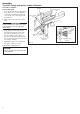
Assembly Throttle Linkage and Ignition Leads All Models Assemble and Adjust the Throttle Cable. 1. Insert the throttle-cable housing into the notch on the fan cover, and clamp the ground wire terminal between the fan cover and the outer cable adjuster nut. See Figure 13. Red Wire Black Ignition Wire Cable Adjuster Nuts 2. Tighten the two throttle cable adjuster nuts. IMPORTANT! Adjust and tighten the cable nuts to allow approximately 1/4-inch free play at the throttle trigger. 3.
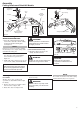
Assembly Cutting Attachment Shield All Models Socket-Head Cap Screw T230 Outer Tube Upper Clamp Cutting Attachment Shield Bracket Shim Shim Nuts Clamp Screw Line Cutter Shim Shim Retaining Nut T230X/C230 Bolt Cutting Attachment Shield Mounting Plate Figure 14 Install the Cutting Attachment Shield T230/T230X/C230. 1. Insert the cutting attachment shield between the outer tube and the cutting attachment shield mounting plate. See Figure 14.
Assembly Trimmer Head C230/T230/T230X Model Holder Remove the T230 retaining plug Output Shaft Shaft Bolt Bolt Guard Model C230/T230X Output Shaft Holder B 5. Using hand pressure only, tighten the trimmer head firmly on the gearshaft. Holder A 6. Remove the hex wrench. 7. Adjust the trimmer line length to reach no further than the line cutter on the cutting attachment shield. Trim to the correct length if necessary.
Assembly Blade C230/T230X (continued) 5. Install blade holder “B” on the output shaft. See Figure 21. The recess in the holder must completely cover the safety clip, and must fit tightly against the blade. Blade Output Shaft Bolt Guard Blade Holder B 6. Install the bolt guard and then the blade retaining bolt. Using the combination spark plug wrench/screwdriver, tighten the bolt firmly in a counter-clockwise direction. 7. Remove the hex wrench.
Starting the Engine IMPORTANT! Engine ignition is controlled by a two position switch mounted on the throttle housing labeled, “I” for ON or START and “O” for OFF or STOP. Make sure the cutting attachment is clear of obstructions! IMPORTANT! If the engine fails to start after several at tempts with the choke in the closed posi tion, the engine may be flooded with fuel.
Adjusting Engine Idle Idle Adjusting Screw The engine must return to idle speed whenever the throttle lever is released. Idle speed is adjustable, and must be set low enough to permit the engine clutch to disengage the cutting attachment. Idle Speed Adjustment WARNING! Figure 28 The cutting attachment must NEVER rotate at engine idle! If the idle speed cannot be adjusted by the procedure described here, return the unit to your Shindaiwa dealer for inspection. 1.
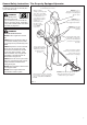
Using a Grass Trimmer T230 Your Shindaiwa T230 Grass Trimmer may be equipped with one of several Shindaiwa trimmer head models, each with features for specific applications and/or operational requirements. NOTE: A grass trimmer head can also be fitted to the Shindaiwa C230 Brushcutter. For proper operation, always refer to the instructions accompanying the trimmer head being used. Available trimmer head styles include: Semi-automatic.
Using A Brushcutter Blade C230/T230X Blade Thrust WARNING! Before working with a bladeequipped unit, always inspect and clean the area of objects that could interfere with or damage the blade. Never use a blade near sidewalks, fence posts, buildings or other objects that could cause injury or damage. Never use a blade for purposes other than those for which it was designed. Whenever you strike a hard ob ject with a blade, always stop the brushcutter and carefully inspect the blade for damage.
General Maintenance IMPORTANT! MAINTENANCE, REPLACEMENT OR REPAIR OF EMISSION CONTROL DEVICES AND SYSTEMS MAY BE PERFORMED BY ANY REPAIR ESTABLISHMENT OR INDIVIDUAL; HOWEVER, WARRANTY REPAIRS MUST BE PERFORMED BY A DEALER OR SERVICE CENTER AUTHORIZED BY SHINDAIWA CORPORATION THE USE OF PARTS THAT ARE NOT EQUIVALENT IN PERFORMANCE AND DURABILITY TO AUTHORIZED PARTS MAY IMPAIR THE EFFECTIVENESS OF THE EMISSION CONTROL SYSTEM AND MAY HAVE A BEARING ON THE OUTCOME OF A WARRANTY CLAIM.
10/15-Hour Maintenance Ever y 10 to 15 hours of operation: Remove and clean the spark plug. Clean the spark plug and check the gap at the electrode. Adjust the spark plug electrode gap to 0.024-inch (0.6 mm). If the plug must be replaced, use only a Champion CJ8 or equivalent spark plug of the correct heat range. For electromagnetic compliance (EMC), use NGK BMR6A. 0.024-inch (0.
135-Hour Maintenance After ever y 135 hours of operation or if engine becomes hard to start and has low power. The spark arrester screen should be inspected and cleaned. Engine Cover Engine Cover Knob WARNING! Never operate the unit with a damaged or missing muffler or spark arrester! Operating with missing or damaged ex haust components is a fire hazard and could also damage your hearing. 1. Remove the spark plug boot. 2.
Long Term Storage Whenever the unit will not be used for 30 days or longer, use the following procedures to prepare it for storage: Clean external parts thoroughly. Drain all the fuel from the carburetor and the fuel tank. IMPORTANT! All stored fuels should be stabilized with a fuel stabilizer such as STA-BIL™. To remove the remaining fuel from the fuel lines and carburetor and with the fuel drained from the fuel tank. 1. Prime the primer bulb until no more fuel is passing through.
Troubleshooting Guide ENGINE DOES NOT START What To Check Does the engine crank? Possible Cause NO Good compression? Faulty recoil starter. Fluid in the crankcase. YES Remedy Consult with an authorized servicing dealer. Internal damage. NO Loose spark plug. Tighten and re-test. Excess wear on cylinder, piston, rings. Consult with an authorized servicing dealer. NO Fuel incorrect, stale, or contaminated; mixture incorrect.
Troubleshooting Guide (continued) ADDITIONAL PROBLEMS Symptom Poor acceleration. Engine stops abruptly. Engine difficult to shut off. Cutting attachment rotates at engine idle. Excessive vibration. Cutting attachment will not rotate. Possible Cause Remedy Clogged air filter. Clean or replace the air filter. Clogged fuel filter. Replace the fuel filter. Lean fuel/air mixture. Consult with an authorized servicing dealer. Idle speed set too low. Adjust: 2,750 (±250) RPM (min-1).
The following statement only applies to United States and its territories Shindaiwa Corporation Federal Emission Design And Defect Limited Warranty Utility And Lawn And Garden Engines Shindaiwa Corporation warrants to the initial purchaser and each subsequent owner, that this utility equipment engine (herein engine) is designed, built and equipped to conform at the time of initial sale, to all applicable regulations of the U.S.
NOTES 23
® Shindaiwa Inc. 11975 S.W. Herman Rd. Tualatin, Oregon 97062 USA Telephone: 503 692-3070 Fax: 503 692-6696 www.shindaiwa.com Shindaiwa Corporation Head Office: 6-2-11, Ozuka-Nishi Asaminami-Ku, Hiroshima 731-3167, Japan Telephone: 81-82-849-2220 Fax: 81-82-849-2481 ©2006 Shindaiwa, Inc. Part Number 62064-94013 Revision 8/06 Shindaiwa is a registered trademark of Shindaiwa, Inc. Specifications subject to change without notice.