Shindaiwa OWNER’S/OPERATOR’S MANUAL PS344 PowerBroomTM WARNING! X7502891100 05/10 Minimize the risk of injury to yourself and others! Read this manual and familiarize yourself with the contents. Always wear eye and hearing protection when operating this unit.
Introduction The Shindaiwa PS344 PowerBroom is designed and built to deliver superior performance and reliability without compromise to quality, comfort, safety or durability. Shindaiwa engines represent the leading edge of high-performance engine technology, delivering exceptionally high power with remarkably low displacement and weight. As an owner/operator, you’ll soon discover for yourself why Shindaiwa is simply in a class by itself! Contents IMPORTANT! Echo, Inc.
Safety Work Safely A PowerBroom operates at very high speeds and has the potential to do serious damage if misused, abused or mishandled. To reduce the risk of injury, you must maintain control at all times, and observe all safety precautions during operation. Never permit a person without training or instruction to operate this machine! WARNING! WARNING! Never make unauthorized attachment installations. Stay Alert You must be physically and mentally fit to operate this unit safely.
Safety (continued) The Properly Equipped Operator Always protect yourself from hazards such as thorny brush and flying debris by wearing gloves and close fitting clothing that covers arms and legs. Never wear shorts. Don’t wear loose clothing or items such as jewelry that could get caught in machinery or underbrush. Secure long hair so it is above shoulder level. Always wear eye and hearing protection. Shindaiwa recommends wearing a face shield as additional face and eye protection.
Product Description Spark Plug Using the illustration as a guide, familiarize yourself with your machine and its various components. Understanding your machine helps ensure top performance, long service life and safer operation. PS344 Grip Handle Ignition Switch Fuel Tank Outer Tube Sweeper Belt Tank Protector Throttle Trigger Gearcase Sweeper Drum WARNING! Do not make unauthorized modifications or alterations to any of these units or their components.
Emission Control (Exhaust & Evaporative) EPA 2010 and Later and/or C.A.R.B. TIER III The emission control system for the engine is EM/TWC (Engine Modification and 3-way Catalyst) and for the fuel tank the Control System is EVAP (Evaporative Emissions) or N (for nylon tank). Evaporative emission may be applicable to California models only. An Emission Control Label is located on the unit. (This is an EXAMPLE ONLY; information on label varies by engine FAMILY).
Assembly (continued) Adjust Throttle Lever Free Play Loosen the air cleaner cover knobs The throttle lever free play should be approximately 3/16-1/4 inch (4-6 mm). Make sure that the throttle lever operates smoothly without binding. If it becomes necessary to adjust the lever free play, follow the procedures and illustrations that follow. 1. Loosen the air cleaner cover knobs and remove the air cleaner cover. 2. Loosen the lock nut on the cable adjuster. 3.
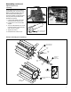
Assembly (continued) 1. Push one of the drum axles onto either of the two gearcase output shafts. If necessary, rotate the drum axle until the clevis pin hole in the axle aligns with the matching hole in the gearcase output shaft. CAUTION! The two drum assemblies are identical, but each drum must be installed with its recessed end facing toward the gearcase. 2. Use a clevis pin and hitch pin to secure the drum axle to the shaft. 3.
Handling Fuel DANGER Fuel is VERY flammable. Use extreme care when mixing, storing or handling or serious personal injury may result. • Use an approved fuel container. • DO NOT smoke near fuel. • DO NOT allow flames or sparks near fuel. • Fuel tanks/cans may be under pressure. Always loosen fuel caps slowly allowing pressure to equalize. • NEVER refuel a unit when the engine is HOT or RUNNING! • DO NOT fill fuel tanks indoors. ALWAYS fill fuel tanks outdoors over bare ground. • DO NOT overfill fuel tank.
Starting the Engine IMPORTANT Engine ignition is controlled by a two position switch mounted on the throttle housing labeled, “I” for ON or START and “O” for OFF or STOP. WARNING! The attachment will operate immediately when the engine starts and could result in possible serious injury. Keep movable parts of the attachment away from objects that could become entangled or thrown, and surfaces that could cause loss of control. WARNING! Never start the engine from the operating position. 1.
Starting the Engine (continued) When the Engine Starts... ■■After the engine starts, allow the engine to warm up at idle 2 or 3 minutes before operating the unit. ■■If the engine does not continue to run, repeat the appropriate cranking procedures for a cold or warm engine.When the engine starts, clear excess fuel from the combustion chamber by accelerating the engine several times with the throttle lever.
Operating Break-in and Operation The PowerBroom works best when its rubber fins can quickly slide or “skim” over the surface being swept. New or replacement sweeper belts tend to grip or drag on hard surfaces, and should be thoroughly broken in or “scuffed” before the broom is actually put to work. Break-in is easily accomplished by operating the PowerBroom at full throttle for 3 to 5 minutes in loose gravel or similar abrasive material.
Maintenance IMPORTANT! MAINTENANCE, REPLACEMENT OR REPAIR OF EMISSION CONTROL DEVICES AND SYSTEMS MAY BE PERFORMED BY ANY REPAIR ESTABLISHMENT OR INDIVIDUAL; HOWEVER, WARRANTY REPAIRS MUST BE PERFORMED BY A DEALER OR SERVICE CENTER AUTHORIZED BY ECHO, INC. THE USE OF PARTS THAT ARE NOT EQUIVALENT IN PERFORMANCE AND DURABILITY TO AUTHORIZED PARTS MAY IMPAIR THE EFFECTIVENESS OF THE EMISSION CONTROL SYSTEM AND MAY HAVE A BEARING ON THE OUTCOME OF A WARRANTY CLAIM.
Maintenance (continued) 10/15-Hour Maintenance Remove and clean or replace the spark plug. ■■Adjust the spark plug electrode gap to 0.024 inch (0.6 mm). If the spark plug must be replaced, use only an NGK CMR5H or equivalent resistor type spark plug of the correct heat range. 0.024 inch (0.6 mm) CAUTION! Before removing the spark plug, clean the area around the plug to prevent dirt and debris from getting into the engine’s internal parts. Clean the spark plug and check the gap at the electrode.
Maintenance (continued) 135 hour maintenance (cont.) Valve Adjustment 1. Remove cylinder cover, rocker arm cover, and spark plug. Rotate the crankshaft while observing the piston through the spark plug opening. When the piston is at the top of the compression stroke (TDC), the valves can be adjusted. CAUTION! ■■Performing a valve adjustment incorrectly may cause hard starting and/or can damage the engine.
Maintenance (continued) Muffler Maintenance If the engine becomes sluggish and low on power, check and clean the spark arrester screen. WARNING! Never operate the unit with a damaged or missing muffler or spark arrester! Operating with a missing or damaged spark arrester is a fire hazard and could also damage your hearing. Engine Cover Engine Cover Screws 1. With a 3 mm hex wrench remove the 3 engine cover screws and the engine cover. 2.
Adjusting Engine Idle The engine must return to idle speed whenever the throttle lever is released. Idle speed is adjustable, and must be set low enough to permit the engine clutch to disengage the attachment. WARNING! The attachment must NEVER rotate at engine idle! If the idle speed cannot be adjusted by the procedure described here, return the trimmer to your Shindaiwa dealer for inspection. Idle Speed Adjustment 1.
Troubleshooting Guide EnGinE dOES nOT STaRT OR haRd TO STaRT Remedy Possible Cause What To Check Vaporlock. Valve adjustment. Engine hot/heat soaked. Let cool completely and restart. Low fuel quality. Refill with fresh, clean unleaded gasoline with a pump octane of 89 or higher mixed with an air cooled engine oil that meets or exceeds ISO-L-EGD and/or JASO FD classified oils at 50:1 gasoline/oil ratio. Valve clearance too tight. Consult with an authorized Shindaiwa servicing dealer. Adjust valves.
Troubleshooting Guide (continued) LOw POwER OUTPUT What To Check Is the engine overheating? Engine is rough at all speeds. May also have black smoke and/or unburned fuel at the exhaust. Possible Cause Remedy Operator is overworking the unit. Use a lower throttle setting. Carburetor mixture is too lean. Consult with an authorized Shindaiwa servicing dealer. Improper fuel ratio.
Troubleshooting Guide (continued) addiTiOnaL PROBLEMS Symptom Poor acceleration. Engine stops abruptly. Possible Cause Clogged air filter. Clean the air filter. Clogged fuel filter. Replace the fuel filter. Lean fuel/air mixture. Consult with an authorized Shindaiwa servicing dealer. Idle speed set too low. Adjust idle. Check Specifications page for correct idle speed. Ignition switch turned off. Reset the switch and re-start. Fuel tank empty.
SHINDAIWA LIMITED WARRANTY STATEMENT FOR PRODUCT SOLD IN USA AND CANADA BEGINNING 01/01/2010 ECHO, INC'S RESPONSIBILITY ECHO Incorporated’s (ECHO, INC.) Limited Warranty, provides to the original purchaser that this Shindaiwa product is free from defects in material and workmanship. Under normal use and maintenance from date of purchase, ECHO, INC.
PURCHASED REPAIR PARTS AND ACCESSORIES • 90-day all applications ATTENTION ENGINE POWERED PRODUCT OWNERS This Shindaiwa engine powered product is a quality-engineered unit which has been manufactured to exact tolerances to provide superior performance. To help ensure the performance of the unit, it is required to use engine oil which meets the ISO-L-EGD Standard per ISO/CD 13738 and JASO M345/FD Standards.
ECHO INCORPORATED EMISSION CONTROL WARRANTY STATEMENT FOR ECHO AND SHINDAIWA BRANDS The Environmental Protection Agency (EPA) and the California Air Resources Board (C.A.R.B.) and ECHO Incorporated (ECHO Inc.) are pleased to explain the emission control system warranty on your 2010 and later equipment/small off-road engine (SORE). New equipment/SORE must be designed, built and equipped to meet stringent EPA and C.A.R.B. anti-smog standards. ECHO Inc.
NOTES 24
NOTES 25
NOTES 26
NOTES 27
Servicing Information Parts/Serial Number Genuine Shindaiwa Parts and Assemblies for your Shindaiwa products are available only from an Authorized Shindaiwa Dealer. When you do need to buy parts always have the Model Number, Type and Serial Number of the unit with you. You can find these numbers on the engine. For future reference, write them in the space provided below.