
Broom Owner's/Operator's Manual


6
IMPORTANT!
The terms “left”, “left-hand”, and
“LH”; “right”, “right-hand”, and “RH”;
“front” and “rear” refer to directions as
viewed by the operator during normal
operation.
WARNING!
Do not make unauthorized
modications or alterations to your
machine or its components.
Before assembling, make sure you have
all the components required for a com-
plete unit:
PowerBroomUnit ■
Assembly
Prior to assembly
Kit containing hardware, owner/ ■
operator's manual, tool kit for rou-
tine maintenance. Tool kits vary
by model and may inclue a hex
wrench, spanner, and a combina-
tion spark plug wrench/screwdriver.
Carefully inspect all components for
■
damage before assembling.
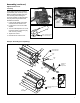
Adjustable Handle
This unit comes with the handle
installed. It can be re-adjusted for
operator comfort in the following
manner.
Loosen adjustment knob. 1. Locate
the handle at the best position for
operator comfort (usually about
10 inches ahead of the throttle
lever), and secure it by tightening
the adjustment knob at the handle
base.
Handle
Hex Nut
Washer
Outer Tube
Adjustment Knob
Mounting Screw
Throttle Assembly
Washer
An Emission Control Label is located on the unit. (This is an EXAMPLE ONLY; information on label varies by en-
gine FAMILY).
PRODUCT EMISSION DURABILITY (EMISSION COMPLIANCE PERIOD)
The 300 hour emission compliance period is the time span selected by the manufacturer certifying the engine
emissions output meets applicable emissions regulations, provided that approved maintenance procedures are
followed as listed in the Maintenance Section of this manual.
Emission Control (Exhaust & Evaporative)
EPA 2010 and Later and/or C.A.R.B. TIER III
The emission control system for the engine is EM/TWC (Engine Modication and 3-way Catalyst) and for the fuel tank
the Control System is EVAP (Evaporative Emissions) or N (for nylon tank). Evaporative emission may be applicable to
California models only.