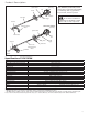
SHINDAIWA OWNER’S/OPERATOR'S MANUAL T272/EVC TRIMMER T272X/EVC TRIMMER T272 T272X WARNING! Minimize the risk of injury to yourself and others! Read this manual and familiarize yourself with the contents. Always wear eye and hearing protection when operating this unit.
Introduction Attention Statements The Shindaiwa 272-series hand-held Power Equipment has been designed and built to deliver superior performance and reliability without compromise to quality, comfort, or durability. Throughout this manual are special “attention statements”. Shindaiwa high performance engines represent the leading edge of 2-cycle engine technology, delivering exceptionally high power from remarkably low displacement and weight.
General Safety Instructions Work Safely Trimmers and brushcutters operate at very high speeds and can do serious damage or injury if they are misused or abused. Never allow a person without training or instruction to operate your unit! Stay Alert You must be physically and mentally fit to operate this unit safely.
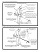
The Properly Equipped Operator Wear close-fitting clothing to protect legs and arms. Gloves offer added protection and are strongly recommended. Do not wear clothing or jewelry that could get caught in machinery or underbrush. NEVER wear shorts! Wear hearing protection devices and a broad-brimmed hat or helmet. Always wear eye protection such as goggles or safety glasses. Always wear a shoulder strap or a harness when operating a unit equipped with a blade.
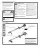
Product Description T272 Grass Trimmer Ignition Switch Spark Plug Grip Handle Fuel Tank Outer Tube Using the accompanying illustrations as a guide, familiarize yourself with your unit and its various components. Understanding your unit helps ensure top performance, long service life, and safer operation. WARNING! Do not make unauthorized modifications or alterations to either of these units or their components.
Assembly Prior to Assembly This unit comes fully assembled with the exception of the cutting attachment shield and cutting attachment. Before assembling, make sure you have all the components required for a complete unit and inspect unit and components for any damage. ■ Engine and shaft assembly ■ Cutting attachment shield ■ Cutting attachment ■ Kit containing cutting attachment IMPORTANT! shield bracket and hardware, this owner's/opertor's manual and tool kit for routine maintenance.
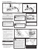
Assembly (continued) Cutting Attachment Shield T272/T272X SocketHead Cap Screw Outer Tube T272 T272X Bolt Cutting Attachment Shield Upper Clamp Bracket Shim Shim Cutting Attachment Shield Nuts Clamp Screw Shim Cutting Attachment Mounting Plate Shim Line Cutter Nut Figure 8a Retaining Nut Figure 8 Line Cutter 26013 1. Insert the cutting attachment shield between the outer tube and the cutting attachment mounting plate. See Figure 8.
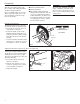
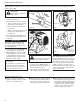
Assembly (continued) Mount the Cutting Blade T272X Turn the T272X upside down so the gearcase output shaft is facing UP and remove the shaft bolt, bolt guard and holder B from the gearcase shaft. Shaft Bolt Slide the safety clip off-center Bolt Guard 1. Align the hole in blade holder A with the matching hole in the gearcase flange and then temporarily lock the output shaft by inserting a hex wrench through both holes. See Figure 12. Output Shaft Holder B Gear Shaft Safety Clip Safety Clip .
Mixing fuel CAUTION! CAUTION! ■ Never use any type of gasoline This engine is designed to operate on a 50:1 mixture consisting of unleaded gasoline and ISO-L-EGD or JASO FC class 2-cycle mixing oil only. Use of non-approved mixing oils can lead to excessive carbon deposits. ■ containing more than 10% alcohol by volume! Some types of gasoline contain alcohol as an oxygenate. Oxygenated gasoline may cause increased operating temperatures.
Starting the Engine IMPORTANT! Engine ignition is controlled by a two-position on-off switch mounted on the throttle body. This switch is typically labeled “I” for ON and “O” for OFF. WARNING! Never start the engine from the operating position. T272/T272X IGNITION SWITCH ON Return Tube 1. Slide the ignition switch to the “ON” position. See Figure 16. . Set the throttle lever to the “fast idle”: a. Squeeze the throttle lever toward the handgrip on the shaft tube. b.
Stopping the Engine IGNITION SWITCH OFF T272/T272X Idle the engine briefly before stopping (about 2 minutes), then slide the ignition switch to the “O” (OFF) position. See Figure 20. 27029 Figure 20 Engine Idle Adjustment The engine must return to idle speed whenever the throttle lever is released. Idle speed is adjustable, and must be set low enough to permit the engine clutch to disengage the cutting attachment when the throttle is released.
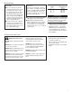
Operation Shoulder Strap T272X IMPORTANT! NOTE: Shoulder Strap recommended for use with grass trimmers Adjust the shoulder strap or harness so the shoulder pad rests comfortably on the off-side shoulder and the cutting path of the cutting attachment is parallel to the ground. Make sure all hooks and adjustment devices are secure. Although a shoulder strap accessory is not required for use with a grass trimmer, a shoulder strap can increase operator comfort during extended periods of operation.
Operation (continued) Using a Blade T272X WARNING! ■ Whenever you strike a hard object with ■ Before working with a blade■ ■ equipped unit, always inspect and clean the area of objects that could interfere with or damage the blade. Never use a blade near sidewalks, fence posts, buildings or other objects that could cause injury or damage. Never use a blade for purposes other than those for which it was designed. ■ ■ a blade, always stop the brushcutter and carefully inspect the blade for damage.
Maintenance General Maintenance IMPORTANT! MAINTENANCE, REPLACEMENT OR REPAIR OF EMISSION CONTROL DEVICES AND SYSTEMS MAY BE PERFORMED BY ANY REPAIR ESTABLISHMENT OR INDIVIDUAL; HOWEVER, WARRANTY REPAIRS MUST BE PERFORMED BY A DEALER OR SERVICE CENTER AUTHORIZED BY SHINDAIWA CORPORATION THE USE OF PARTS THAT ARE NOT EQUIVALENT IN PERFORMANCE AND DURABILITY TO AUTHORIZED PARTS MAY IMPAIR THE EFFECTIVENESS OF THE EMISSION CONTROL SYSTEM AND MAY HAVE A BEARING ON THE OUTCOME OF A WARRANTY CLAIM.
Maintenance (continued) 50 Hour Maintenance Perform more frequently in dusty or dirty conditions. ■ Remove and clean the cylinder cover and clean grass and dirt from the cylinder fins. ■ Remove the cutting attachment, cut- New Grease ting attachment holder and gear shaft collar. Remove the filler plug from the side of the gearcase and press new grease into the gearcase until old grease is pushed out. Use only lithium-base grease such as Shindaiwa Gearcase Lubricant or equivalent.
Long Term Storage Whenever the unit will not be used for 30 days or longer, use the following procedures to prepare it for storage: ■ Clean external parts thoroughly. ■ Drain all the fuel from the fuel tank. IMPORTANT! All stored fuels should be stabilized with a fuel stabilizer such as STA-BIL™ , if oil with fuel stabilizer is not used. CAUTION! Gasoline stored in the carburetor for extended periods can cause hard starting and could also lead to increased service and maintenance costs.
Troubleshooting Guide What To Check ENGINE DOES NOT START Possible Cause Faulty recoil starter. Does the engine crank? NO Remedy Consult with an authorized servicing dealer. Fluid in the crankcase. Internal damage. YES Good compression? Loose spark plug. Tighten and re-test. Excess wear on cylinder, piston, rings. Consult with an authorized servicing dealer. NO Fuel incorrect, stale, or contaminated; mixture incorrect.
Troubleshooting Guide (continued) LOW POWER What To Check Is the engine overheating? Engine is rough at all speeds. May also have black smoke and/or unburned fuel at the exhaust. Possible Cause Operator is overworking the unit. Cut at slower rate. Carburetor mixture is too lean. Consult with an authorized servicing dealer. Improper fuel ratio. Refill with clean fresh unleaded gasoline with a pump octane of 87 or higher, mixed with Premium 2-cycle mixing oil at a 50:1 gasoline/oil ratio.
Troubleshooting Guide (continued) ADDITIONAL PROBLEMS What To Check Possible Cause Clogged air filter. Poor acceleration. Clogged fuel filter. Lean fuel/air mixture. Idle speed set too low. Engine stops abruptly. Engine difficult to shut off. Cutting attachment moves at engine idle. Excessive vibration. Remedy Clean or replace the air filter. Replace the fuel filter. Consult with an authorized servicing dealer. Adjust:3,000 (±300) min-1. Switch turned off. Reset the switch and re-start.
Emission System Warranty Statement Your Warranty Rights and Obligations Owners Warranty Responsibilities The California Air Resources Board, the U.S. Environmental Protection Agency and Shindaiwa Corporation are pleased to explain the exhaust and evaporative emission control system warranty on your new small off-road (non-road) engine. In California, new small off-road engines must be designed, built, and equipped to meet the State’s stringent anti-smog standards.
Declaración de Garantía del Sistema de Emisión Como propietario del motor pequeño (no para el uso en automóviles), es usted responsable por el rendimiento del mantenimiento requerido y mencionado en este manual del propietario.
Guia Diagnostico (continuación) Otros problemas Qué revisar Deficiente aceleración. El motor se detiene abruptamente. Difícil apagado del motor. El accesorio de corte se mueve al ralentí del motor. Excesiva vibración. El accesorio no gira. Posible causa Remedio Reemplace muelle/zapatas según sea necesario; compruebe el ralentí. Resorte del embrague roto o resalte desgastado. Fije el ralentí: 2.750 (±250) min-1. Ralentí demasiado alto. Deje el motor al ralentí hasta que se enfríe.
Guia Diagnostico (continuación) BAJA POTENCIA Qué revisar ¿Se sobrecalienta el motor? Posible causa Remedio Consulte con un agente de servicio autorizado. La mezcla del carburador es muy pobre. Corte más despacio. Unidad sobrecargada por el usuario. Limpie o reemplace el filtro de aire. Filtro de aire obstruido. Consulte con un agente de servicio autorizado. Depósitos de carbonilla en el pistón o el silenciador. Limpiar, reparar o sustituir en caso necesario.
Guia Diagnostico El Motor No Arranca Qué revisar ¿Arranca el motor? NO Posible causa Arrancador autorretráctil defectuoso. Líquido en el cárter. Remedio Consulte a un agente de servicio de Shindaiwa. Daños internos. SÍ ¿Hay buena compresión? NO Bujía suelta. Desgaste excesivo en el cilindro, el pistón o los anillos. SÍ ¿Contiene el tanque combustible fresco y con el octanaje correcto? NO Combustible incorrecto, viejo o contaminado; mezcla incorrecta.
Almacenamiento de Largo Plazo Cada vez que la máquina no va a ser usada por 30 días o más, siga los siguientes procedimientos para preparar su almacenamiento: ■ Limpie las partes externas minuciosamente. ■ Drene todo combustible en el tanque. ¡Importante! Todo combustible almacenado debe estar estabilizado con un estabilizador de combustible tal como STA-BIL™ , al menos que use aceite con estabilizador de combustible.
Mantenimiento (continuación) Mantenimiento Cada 50-Horas Cada 50 horas de operación (más frecuentemente bajo condiciones sucias o polvorientas): ■ Retire y limpie la tapa del cilindro y limpie la maleza y la suciedad en las aletas del cilindro. ■ Retire el accesorio de corte, el soporte y el collar del eje de la caja de engranajes. Retire el perno de grasa al lado de la caja de engranajes e introduzca nueva grasa en la caja de engranajes hasta que la grasa usada salga. Use solamente grasa a base de litio.
Mantenimiento Mantenimiento General ¡Importante! EL MANTENIMIENTO, REEMPLAZO O REPARACION DE LOS SISTEMAS Y DISPOSITIVOS DE CONTROL DE EMISION PUEDEN SER EFECTUADOS POR CUALQUIER ESTABLECIMIENTO O INDIVIDUO; SIN EMBARGO, LAS REPARACIONES DE GARANTIA DEBEN SER EFECTUADAS POR SU CENTRO DE SERVICIO O DISTRIBUIDOR AUTORIZADO POR SHINDAIWA CORPORTATION.
Operación (continuación) Usando un disco (T272X) ¡ADVERTENCIA! ■ ■ ■ Antes de trabajar con una unidad equipada con un disco, siempre inspeccione y limpie los objetos en el área que puedan interferir o dañar el disco. NUNCA use un disco cerca de veredas, cercas, edificios u otros objetos que puedan causar lesiones o daños. NUNCA use un disco para ningún otro propósito aparte del cual ha sido diseñado.
Operación Arnés ¡Importante! Ajuste el arnés de tal forma que la almohadilla descanse cómodamente sobre los lados de los hombros y que la trayectoria de corte del accesorio de corte esté paralelo al suelo. Asegure que todo los ganchos y dispositivos de ajuste estén asegurados. Arnés recomendado para una podadora. ¡Advertencia! Siempre use un arnés cuando opere esta unidad con una cuchilla. Unarnés es también recomendado cuando use cable de nylon.
Parada del Motor Ponga el motor en marcha mínima por dos o tres minutos antes de apagarlo, luego deslice el interruptor de ignición a la posición “O” (motor apagado). Consulte la figura 20. Interruptor de Encendido (Apagado) 27023 Figura 20 Ajuste de Marcha Mínima del Motor El motor debe retornar a marcha mínima cuando la palanca del acelerador es liberada. La marcha mínima es ajustable y debe ser suficientemente mínima para permitir que el embrague del motor libere el accesorio de corte. .
Arranque del Motor NOTA: El encendido del motor está controlado por un interruptor de dos posiciones montado en el mango del acelerador indicado “I” (encendido) y “O” (apagado). ¡Advertencia! Nunca arranque el motor desde la posición de operación. T272/T272X Tubo de retorno Encendido 1. Deslice el interruptor hacia la posición ‘I’ (motor encendido). Consulte la figura 16. . Posicione la palanca del acelerador en "marcha rápida" como a continuación: a.
Mezcla de Combustible Este motor está diseñado solamente para funcionar con una mezcla de 50:1 de gasolina sin plomo y aceite de mezclar para motores de 2 tiempos. ISO-L-EGD o JASO FC. El uso de aceites de mezclar no autorizados puede conducir a excesos de depósitos de carbón. Nunca use ningún combustible que contenga más de 10% de alcohol por volumén! Algunas gasolinas contienen alcohol como un oxigenante. Combustibles oxigenados pueden aumentar la temperatura del motor durante su funcionamiento.
Ensamblaje: Disco/Cuchilla T272X Monte la Cuchilla de Corte Ponga la T727X de cabeza, de tal forma que el perno del eje de la caja de engranajes este cara arriba y retire el perno del eje, el protector de perno y el soporte "B" del eje de la caja de engranajes. 1. Alinie la muesca en el Soporte "A" con la muesca correspondiente en el borde de la caja de engranajes y luego asegure temporalmente el eje de salida insertando la llave hexagonal a traves de ambas muescas. Consulte la figura 12.
Ensamblaje Protector del Accesorio de Corte T272/T272X Tornillo de cabeza hexagonal Tubo Exterior T272 Protector del accesorio de corte Soporte Tornillo T272X Soporte Espaciador Espaciador Protector del accesorio de corte Tuercas Tornillo de la abrazadera Espaciador Retén Placa de montaje del accesorio de corte Espaciador Cuchia de corte Retén Figure 8a Figure 8 Cortador de nylon 26013 1. Inserte el protector del accesorio de corte entre el tubo exterior y la placa de montaje.
Ensamblaje Antes de Ensamblar Esta unidad viene completamente en- samblada con la excepción del accesorio de corte y el protector del accesorio de corte. Antes de ensamblar, cerciórese de que tenga todos los componentes necesarios para armar una máquina completa e inspeccione la unidad y componentes en busca de danos.
Descripción del Producto Interruptor de Encendido Mango Podadora T272 Bujía Manillar Tanque de Combustible Tubo Exterior Gatillo del Acelerador Caja de Engranajes Podadora T272X Protector del Accesorio de Corte Use las ilustraciones como guía, familiarícese con esta unidad y sus varios componentes. Conociendo mejor la unidad le ayudará a obtener alto rendimiento, mayor vida útil y mejor operación.
El Operario Debidamente Equipado Use un protector auditivo y un casco o sombrero. Use ropa de su talla para proteger su piernas y brazos. Los guantes siempre proveen protección adicional y son altamente recomendados. No use ropa holgada o joyas que puedan atascarse en la máquina o en la vegetación. NUNCA use pantalones cortos. Mantenga una posición apropiada y nunca extienda el cuerpo, mantenga su balance en todo momento durante el uso de la máquina.
Instrucciones Generales de Seguridad Trabaje con cuidado Podadoras y desmalezadoras operan a velocidades altas y pueden causar daños o lesiones serias si son mal usadas o abusadas. Nunca permita que una persona sin entrenamiento o instrucción opere esta unidad! Mantengase Alerta Debe de estar físicamente y mentalmente en optimas condiciones para operar esta máquina con seguridad.
A travéz de este manual se encuentran “declaraciones de seguridad” especiales. La desmalezadora Shindaiwa Serie 272 ha sido diseñada y construída para suministrar un rendimiento superior sin comprometer calidad, comodidad ni durabilidad. Declaraciones de Seguridad Introducción Los motores Shindaiwa representan la tecnología líder de motores de alto rendimiento, de poco peso y pequeña cilindrada con excepcional alta potencia.
Manual Del Propietario/Operador Shindaiwa Podadora T272/EVC Podadora T272X/EVC T272 T272X ¡Advertencia! Disminuya el riesgo de su-frir lesiones o causar lesiones a otros! Lea este manual y familiarícese con su contenido. Siempre use protección para los ojos y oídos cuando opere esta máquina. Numero de part 81606 Rev.