SHINDAIWA OWNER’S/OPERATOR’S MANUAL EB854 BLOWER EB854RT BLOWER EB854RT EB854 WARNING! Minimize the risk of injury to yourself and others! Read this manual and familiarize yourself with the contents. Always wear eye and hearing protection when operating this unit.
Introduction The Shindaiwa EB854 has been designed and built to deliver superior performance and reliability without compromise to quality, comfort, safety, or durability. The information contained in this manual describes units available at the time of production. While every attempt has been made to give you the very latest information about your Shindaiwa EB854 blower. There may be some differences between your EB854 blower and what is described here.
General Safety Instructions Work Safely Blowers operate at a very high speed and can do serious damage or injury if they are misused or abused. Never allow a person without training or instruction to operate your Blower! Stay Alert You must be physically and mentally fit to operate this unit safely. WARNING! Never make unauthorized modifications or attachment installations. Never use attachments not approved by Shindaiwa for use on this unit.
Safety Labels IMPORTANT! Safety and Operation Information Labels: Make sure all information labels are undamaged and readable. Immediately replace damaged or missing information labels. New labels are available from your local authorized Shindaiwa dealer. WARNING! Metal surfaces of crankcase may be hot! Always wear gloves when handling this unit. The Properly Equipped Operator Wear close-fitting clothing to protect legs and arms. Gloves offer added protection and are strongly recommended.
Be Aware of the Working Environment Debris sometimes collects on the blower intake. Never clean out debris from the blower while the engine is running! Make sure bystanders or observers outside the 15m (50-foot) “danger zone” wear 15 METERS Avoid long-term operation in very hot or very cold weather. Never operate the blower if any component parts are damaged, loose, or missing! Be extremely careful of slippery terrain, especially during rainy weather.
Unit Description Using this illustration as a guide, familiarize yourself with the blower and its components. Understanding the unit helps ensure top performance, longer service life, and safer operation.
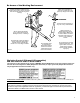
Assembly Prior to Assembly Before assembling the blower, make sure you have all required components. ■■Power unit and blower assembly. ■■Flexible tube, swivel tube, two nozzles and straight tube. ■■Handgrip. ■■Two tube clamps (102 and 89 mm). ■■This Owner’s/Operator’s Manual and a tool kit containing a tool bag, 4 mm hex wrench, 5 mm hex wrench and a combination spark plug wrench/screwdriver. ■■Lead wire assembly (anti-static). Carefully inspect all components for damage.
Assembly Assembling the EB854RT IMPORTANT! This unit is equipped with a static discharge reduction wire. This wire helps direct static buildup into the air stream reducing the felt amount to the operator. Swivel Tube 1. Place the blower upright on the ground or a sturdy work surface and note parts orientation as shown in Figure 7. Flexible Tube 3. Turn the discharge tube out to a right angle and slip anti-static wire through the 102mm clamp and flexible tube. 4.
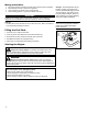
Mixing Fuel WARNING! Alternative fuels, such as E15 (15% ethanol), E-85 (85% ethanol) or any fuels not meeting Shindaiwa requirements are NOT approved for use in Shindaiwa gasoline engines. Use of alternative fuels may cause performance problems, loss of power, overheating, fuel vapor lock, and unintended machine operation, including, but not limited to, improper clutch engagement. Alternative fuels may also cause premature deterioration of fuel lines, gaskets, carburetors and other engine components.
Mixing Instructions 1. 2. 3. 4. Fill an approved fuel container with half of the required amount of gasoline. Add the proper amount of engine oil to gasoline. Close container and shake to mix oil with gasoline. Add remaining gasoline, close fuel container, and remix. IMPORTANT! Spilled fuel is a leading cause of hydrocarbon emissions. Some states may require the use of automatic fuel shut-off containers to reduce fuel spillage. After use • DO NOT store a unit with fuel in its tank. Leaks can occur.
Starting the Engine Starting Procedure 1. Place the blower on the ground. Full Throttle EB854 Pull upward rapidly 2. Prime the fuel system by repeatedly depressing the fuel primer bulb until no air bubbles are visible in the fuel discharge line. IMPORTANT! The primer system only pushes fuel through the carburetor. Repeatedly pressing the primer bulb will not flood the engine with fuel.
Throttle Control EB854RT The EB854RT blower is equipped with a multi- function throttle control. The “Cruise” function allows the operator to use a thumb controlled lever for constant speed use without using the throttle trigger. This is useful for limiting the fatigue caused from holding the throttle for extended periods of time.
Using The Blower Operating Tips In the hands of an experienced operator, the blower can efficiently move a wide variety of debris ranging from grass clippings to gravel. As a general rule, operate your blower at the lowest throttle setting required to get the job done: Heat sensor This engine is equipped with a heat sensor in order to prevent overheating. If engine overheating occurs, the engine speed will be reduced to 5,000 RPM, and engine stops after 10 seconds.
Maintenance (continued) Daily Maintenance WARNING! To reduce fire hazard, keep the engine and muffler free of dirt, debris, and leaves. Prior to each workday, perform the following: ■■Remove all dirt and debris from blower exterior and the engine. Check the cooling fins and air cleaner for clogging and clean as necessary. ■■Inspect the engine, tank, and hoses CAUTION! for possible fuel leaks, and repair as necessary. The engine is cooled by air drawn into the air intake cover on the blower housing.
Maintenance (continued) Every 50 Hours (more frequently if reduced performance is noted) ■■INSPECTION Inspect the entire blower and tubes for damage, including loose or missing components, and repair as necessary. ■■SPARK PLUG Replace the spark plug with a NGK CMR5H (or equivalent), gapped to 0.6 mm (0.024”). ■■FUEL FILTER Use a hooked wire to extract the fuel filter from inside the fuel tank. See Figure 21. ■■Inspect the filter element for signs of contamination from debris.
135 Hour Valve Adjustment ■■Combustion chamber should be decarbonized, and the valve clearance should be adjusted. It is highly recommended that this is done by a Shindaiwa-trained service technician. ■■Replace the spark plug annually: Use only the type recommended in the ”Specifications” section or an equivalent resistor type spark plug of the correct heat range. Set spark plug electrode gap to 0.6 mm (0.024 in). IMPORTANT! The valve clearance should be adjusted.
Long Term Storage Whenever the unit will not be used for 30 days or longer, use the following procedures to prepare it for storage: • Clean external parts thoroughly. • Drain all the fuel from the fuel tank. IMPORTANT! Stored fuel ages. Do not mix more fuel than you expect to use in thirty (30) days, ninety (90) days when a fuel stabilizer is added. • Remove the remaining fuel from the fuel lines and carburetor. 1. Prime the primer bulb until no more fuel is passing through. 2.
Troubleshooting Guide ENGINE DOES NOT START OR HARD TO START Possible Cause What To Check Vaporlock. Valve adjustment. Remedy Engine hot/heat soaked. Let cool completely and restart. Low fuel quality. Refill with fresh, clean unleaded gasoline with a pump octane of 89 or higher mixed with an air cooled engine oil that meets or exceeds ISO-L-EGD and/or JASO FD classified oils at 50:1 gasoline/oil ratio. Valve clearance too tight. Consult with an authorized Shindaiwa servicing dealer.
Troubleshooting Guide (continued) LOW POWER OUTPUT What To Check Is the engine overheating? Engine is rough at all speeds. May also have black smoke and/or unburned fuel at the exhaust. Possible Cause Remedy Operator is overworking the unit. Use a lower throttle setting. Carburetor mixture is too lean. Consult with an authorized Shindaiwa servicing dealer. Improper fuel ratio.
Troubleshooting Guide (continued) ADDITIONAL PROBLEMS Symptom Poor acceleration. Engine stops abruptly. Possible Cause Clogged air filter. Clean the air filter. Clogged fuel filter. Replace the fuel filter. Lean fuel/air mixture. Consult with an authorized Shindaiwa servicing dealer. Idle speed set too low. Adjust idle. Check Specifications page for correct idle speed. Ignition switch turned off. Reset the switch and re-start. Fuel tank empty.
SHINDAIWA LIMITED WARRANTY STATEMENT FOR PRODUCT SOLD IN USA AND CANADA BEGINNING 01/01/2010 ECHO, INC’S RESPONSIBILITY ECHO Incorporated’s (ECHO, INC.) Limited Warranty, provides to the original purchaser that this Shindaiwa product is free from defects in material and workmanship. Under normal use and maintenance from date of purchase, ECHO, INC.
PURCHASED REPAIR PARTS AND ACCESSORIES • 90-day all applications ATTENTION ENGINE POWERED PRODUCT OWNERS This Shindaiwa engine powered product is a quality-engineered unit which has been manufactured to exact tolerances to provide superior performance. To help ensure the performance of the unit, it is required to use engine oil which meets the ISO-L-EGD Standard per ISO/CD 13738 and JASO M345/FD Standards.
ECHO INCORPORATED EMISSION CONTROL WARRANTY STATEMENT FOR ECHO AND SHINDAIWA BRANDS The Environmental Protection Agency (EPA) and the California Air Resources Board (C.A.R.B.) and ECHO Incorporated (ECHO Inc.) are pleased to explain the emission control system warranty on your 2010 and later equipment/small off-road engine (SORE). New equipment/SORE must be designed, built and equipped to meet stringent EPA and C.A.R.B. anti-smog standards. ECHO Inc.
NOTES 24
NOTES 25
NOTES 26
NOTES 27
Servicing Information Parts/Serial Number Genuine Shindaiwa Parts and Assemblies for your Shindaiwa products are available only from an Authorized Shindaiwa Dealer. When you do need to buy parts always have the Model Number, Type and Serial Number of the unit with you. You can find these numbers on the engine. For future reference, write them in the space provided below. Model No. _____________ SN.