SHINDAIWA OWNER’S/OPERATOR’S MANUAL C282 BRUSHCUTTER WARNING! X7502825300 07/10 Minimize the risk of injury to yourself and others! Read this manual and familiarize yourself with the contents. Always wear eye and hearing protection when operating this unit.
Introduction The Shindaiwa 282 series is designed and built to deliver superior performance and reliability without compromise to quality, comfort, safety or durability. Shindaiwa engines represent the leading edge of high-performance engine technology, delivering exceptionally high power with remarkably low displacement and weight.
Safety Work Safely Trimmers and brushcutters operate at very high speeds and can do serious damage or injury if they are misused or abused. Never allow a person without training or instruction to operate this unit! WARNING! WARNING! Never make unauthorized attachment installations. Never operate power equipment of any kind if you are tired or if you are under the influence of alcohol, drugs, medication or any other substance that could affect your ability or judgement.
Safety (continued) The Properly Equipped Operator Wear hearing protection devices and a broad-brimmed hat or helmet. A helmet is required when using a blade-equipped brushcutter to clear small trees. Always wear eye protection such as goggles or safety glasses to shield against thrown objects. Always wear a harness when operating the unit . It adds comfort and helps ensure safety by limiting movement fore and aft.
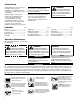
Product Description Using the illustration as a guide, familiarize yourself with your machine and its various components. Understanding your machine helps ensure top performance, long service life and safer operation. C282 Ignition Throttle Throttle interlock Spark plug Muffler Hanger Handlebar Fuel Tank Outer Tube Strap with Protector Gearcase WARNING! Cutting Attachment Shield Brushcutter blade Do not make unauthorized modifications or alterations to any of these units or their components.
Emission Control (Exhaust & Evaporative) EPA 2010 and Later and/or C.A.R.B. TIER III The emission control system for the engine is EM/TWC (Engine Modification and 3-way Catalyst) and for the fuel tank the Control System is EVAP (Evaporative Emissions) or N (for nylon tank). Evaporative emission may be applicable to California models only. An Emission Control Label is located on the unit. (This is an EXAMPLE ONLY; information on label varies by engine FAMILY).
Assembly (continued) Adjust throttle lever free play The throttle lever free play should be approximately 4-6 mm. Make sure that the throttle lever operates smoothly without binding. If it becomes necessary to adjust the lever free play, follow the procedures and illustrations that follow. 1. Loosen the air cleaner cover knob and remove the air cleaner cover. 2. Loosen the lock nut on the cable adjuster. 3. Turn the cable adjuster in or out as required to obtain proper free play. 4. Tighten the locknut. 5.
Assembly (continued) Hand-tighten Trimmer Head (counterclockwise to install) Installing a Trimmer Head NOTE: This unit is shipped with Holder A, Holder B, shaft bolt, and bolt guard installed. The shaft bolt is a LEFTHAND thread. Remove it by turning CLOCKWISE! 1.
Assembly (continued) CAUTION! Install the blade so its printed surface is visible to the operator when the brushcutter is in the normal operating position. IMPORTANT! Discard blades that are bent, warped, cracked, broken or damaged in any way. Use a sharp blade. A dull blade is more likely to snag and thrust. 5. Install the bolt guard and then the blade retaining bolt. Using the combination spark plug wrench/screwdriver, tighten the bolt firmly in a counter-clockwise direction. 6. Remove the hex wrench.
Handling Fuel DANGER Fuel is VERY flammable. Use extreme care when mixing, storing or handling or serious personal injury may result. • Use an approved fuel container. • DO NOT smoke near fuel. • DO NOT allow flames or sparks near fuel. • Fuel tanks/cans may be under pressure. Always loosen fuel caps slowly allowing pressure to equalize. • NEVER refuel a unit when the engine is HOT or RUNNING! • DO NOT fill fuel tanks indoors. ALWAYS fill fuel tanks outdoors over bare ground. • DO NOT overfill fuel tank.
Starting the Engine IMPORTANT! Engine ignition is controlled by a two position switch mounted on the throttle housing labeled, “I” for ON or START and “O” for OFF or STOP. WARNING! Never start the engine from the operating position. 1. Slide the ignition switch to the “I” position. 2. Press the primer bulb until fuel can be seen flowing in the transparent return tube. ON Primer bulb IMPORTANT! The primer system only pushes fuel through the carburetor.
Starting the Engine (continued) Starting A Flooded Engine 1. Slide the ignition switch to the “I” (ON) position. 2. Open the choke, put the throttle lever in the full throttle position, then clear excess fuel from the combustion chamber by cranking the engine several times. 3. If the engine still fails to start or fire, refer to the troubleshooting flow chart at the end of this manual. Stopping the Engine IMPORTANT! OFF 1. Idle the engine briefly before stopping (about 2 minutes). 2.
Operation (continued) Cutting grass with a trimmer head Engine Operating Speeds Your Shindaiwa unit may be equipped with one of several Shindaiwa trimmer head models, each with features for specific applications and/or operational requirements. NOTE: For proper operation, always refer to the instructions accompanying the trimmer head being used. Trimmer head styles: Semi-automatic. Trimmer line is indexed when the operator taps the trimmer head on the ground during operation. Manual.
Blade Thrust “Blade thrust” is a sudden sideways or backward motion of the brushcutter. Such motion may occur when the blade jams or catches on an object such as a sapling tree or tree stump. BE CONSTANTLY ALERT FOR BLADE THRUST AND GUARD AGAINST ITS EFFECTS! WARNING! Blade thrust can occur without warning if the blade snags, stalls or binds. Engine Operating Speeds WARNING! Blade thrust is more likely to occur in areas where it is difficult to see the material being cut.
Maintenance (continued) Muffler This unit must never be operated with a faulty or missing spark arrester or muffler. Make sure the muffler is well secured and in good condition. A worn or damaged muffler is a fire hazard and may also cause hearing loss. Blades Keep blades sharp and check blade condition frequently. If a blade’s performance changes suddenly, stop the engine and check the blade for cracks or other damage.
Maintenance (continued) 10-hour maintenance Perform more frequently in dusty or dirty conditions. Air Filter Element Remove the air cleaner filter. Clean or replace as necessary. To clean filter wash it thoroughly in soap and water. Let it dry before reinstalling the filter. CAUTION! Do not operate the unit if the air cleaner or filter is damaged, or if the filter is wet or water soaked.
Maintenance (continued) 50 hour maintenance Remove and replace the fuel filter element. Before reinstalling the new filter element, inspect the condition of all the fuel system components (fuel pick-up line, fuel return line, tank vent line, tank vent, fuel cap and fuel tank). If damage, splitting or deterioration is noted, the unit should be removed from service until it can be inspected or repaired by a Shindaiwatrained service technician.
Maintenance (continued) 3. With a Phillips type screwdriver, remove the 5 screws holding the spark arrester screen and cover to the muffler. 4. Remove the screen and clean it with a stiff bristle brush. 5. Remove the 3 muffler bolts and the muffler. 6. Inspect the cylinder exhaust port for any carbon buildup. 7. Gently tap the muffler on a wood surface to dislodge any loose carbon. 8. Reassemble the spark arrester, muffler and engine cover in the reverse order of disassembly.
Adjusting Engine Idle The engine must return to idle speed whenever the throttle lever is released. Idle speed is adjustable, and must be set low enough to permit the engine clutch to disengage the cutting attachment. WARNING! The cutting attachment must NEVER rotate at engine idle! If the idle speed cannot be adjusted by the procedure described here, return the trimmer to your Shindaiwa dealer for inspection. Idle Speed Adjustment 1.
Troubleshooting Guide ENGINE DOES NOT START OR HARD TO START Possible Cause What To Check Vaporlock. Remedy Engine hot/heat soaked. Let cool completely and restart. Low fuel quality. Refill with fresh, clean unleaded gasoline with a pump octane of 89 or higher mixed with an air cooled engine oil that meets or exceeds ISO-L-EGD and/or JASO FD classified oils at 50:1 gasoline/oil ratio. ENGINE DOES NOT START Possible Cause What To Check Does the engine crank? NO Internal damage.
Troubleshooting Guide (continued) LOW POWER OUTPUT What To Check Is the engine overheating? Engine is rough at all speeds. May also have black smoke and/or unburned fuel at the exhaust. Possible Cause Operator is overworking the unit. Use a lower throttle setting. Carburetor mixture is too lean. Consult with an authorized Shindaiwa servicing dealer. Improper fuel ratio.
Troubleshooting Guide (continued) ADDITIONAL PROBLEMS Symptom Poor acceleration. Engine stops abruptly. Possible Cause Clogged air filter. Clean the air filter. Clogged fuel filter. Replace the fuel filter. Lean fuel/air mixture. Consult with an authorized Shindaiwa servicing dealer. Idle speed set too low. Adjust idle. Check Specifications page for correct idle speed. Ignition switch turned off. Reset the switch and re-start. Fuel tank empty.
SHINDAIWA LIMITED WARRANTY STATEMENT FOR PRODUCT SOLD IN USA AND CANADA BEGINNING 01/01/2010 ECHO, INC’S RESPONSIBILITY ECHO Incorporated’s (ECHO, INC.) Limited Warranty, provides to the original purchaser that this Shindaiwa product is free from defects in material and workmanship. Under normal use and maintenance from date of purchase, ECHO, INC.
PURCHASED REPAIR PARTS AND ACCESSORIES • 90-day all applications ATTENTION ENGINE POWERED PRODUCT OWNERS This Shindaiwa engine powered product is a quality-engineered unit which has been manufactured to exact tolerances to provide superior performance. To help ensure the performance of the unit, it is required to use engine oil which meets the ISO-L-EGD Standard per ISO/CD 13738 and JASO M345/FD Standards.
DECLARACIÓN DE GARANTÍA LIMITADA DE SHINDAIWA ECHO INCORPORATED EMISSION VIGENTE PARA PRODUCTOS VENDIDOS ENCONTROL ESTADOSWARRANTY UNIDOS Y STATEMENT CANADÁ COMENZAR FOR ECHO SHINDAIWA 1° DEAND ENERO DE 2010BRANDS The Environmental Protection Agency (EPA) and the California Air Resources Board (C.A.R.B.) and ECHO Incorporated (ECHO Inc.) are pleased RESPONSABILIDAD DE ECHO to explain the emission control system warranty on your 2010 and later equipment/small off-road engine (SORE).
NOTES 26
NOTES 27
Servicing Information Parts/Serial Number Genuine Shindaiwa Parts and Assemblies for your Shindaiwa products are available only from an Authorized Shindaiwa Dealer. When you do need to buy parts always have the Model Number, Type and Serial Number of the unit with you. You can find these numbers on the engine. For future reference, write them in the space provided below. Model No. _____________ SN.