PLUG-IN TYPE ALARM DETECTOR SE A SERIES INSTRUCTION MANUAL
Preface Thank you for purchasing the SE A series Alarm Detector. This manual contains instructions for the mounting, functions, operations and notes when operating the SE A series. To ensure safe and correct use, thoroughly read and understand this manual before using this unit. To prevent accidents arising from the misuse of this instrument, please ensure the operator receives this manual. Notes • This instrument should be used in accordance with the specifications described in the manual.
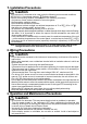
1.
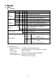
Model Explanation Model names included in this manual are indicated below. Name SE Model SE2EA, SE2RA, SE2AA, SE2VA SE1EA, SE1RA, SE1AA, SE1VA SE2 A SE1 A A series Characters Used in This Manual Indication Number, / Indication Alphabet Indication Alphabet -1 0 1 2 3 4 5 6 7 8 9 A B C D E F G H I J K L M N O P Q R S T U V W X Y Z means that no character is indicated (unlit) on the display.
--- CONTENTS --- 1. Model Page 1.1 Model ---------------------------------------------------------------------------- 6 1.2 How to Read the Model Label --------------------------------------------- 7 2. Name and Functions of Sections ------------------------------------------- 8 3. Mounting 3.1 External Dimensions (Scale: mm) ---------------------------------------- 9 3.2 Mounting to a DIN Rail ------------------------------------------------------ 9 3.
1. Model 1.
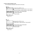
1.2 How to Read the Model Label The model label is attached to the left side of the case. SE2 A Model (E.g. SE2EA-1-0-0) CH1 input (Enter a range selected in “Input range”.) CH2 input (Enter a range selected in “Input range”.) Power supply, Power consumption Ambient temperature Serial number (Fig. 1.2-1) SE1 A Model (E.g. SE1EA-1-0-0) Input (Enter a range selected in “Input range”.) Power supply, Power consumption Ambient temperature Serial number (Fig. 1.
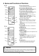
2. Name and Functions of Sections SE2 A (1) (2) (3) (4) (5) (6) (8) (7) (9) (10) (Fig. 2-1) SE1 A (1) (4) (5) (6) (8) (7) (9) (10) (1) Power indicator (Green) Lit when the power to the instrument is turned on. (2) CH1 indicator (SE2 A) (Yellow) Lit when CH1 is selected in [Display selection]. Flashes when CH1 alarm output is ON. (3) CH2 indicator (SE2 A) (Yellow) Lit when CH2 is selected in [Display selection]. Flashes when CH2 alarm output is ON.
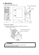
3. Mounting 3.1 External Dimensions (Scale: mm) Socket (sold separately) 85 DIN rail 3 (Fig. 3.1-1) (29) 79 30 108 3.2 Mounting to a DIN Rail (1) Hook the upper part of the socket on the DIN rail, and mount it. (A clicking sound is heard.) Hook the upper part of the socket on the DIN rail. (Fig. 3.2-1) Caution Wire the instrument before inserting the unit into the socket. For wiring, refer to Section “4. Wiring”. -9- 3.
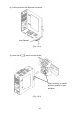
(2) Confirm that the Lock Release is lowered. Lock Release (Fig. 3.2-2) (3) Insert the SE A series into the socket. When inserting, be careful about the position of pins and slots. (Fig. 3.
(4) Fix the SE A series and the socket by pushing the Lock Release up. Check that the SE A series and the socket are locked by pushing the Lock Release up. Lock Release (Fig. 3.2-4) 3.3. Removal from a DIN Rail (1) Turn the power supply to the unit OFF. (2) Pull the Lock Release down, and release the SE A series from the socket. Check that the SE A series and the socket are unlocked by pulling the Lock Release down. Lock Release (Fig. 3.
(3) Separate the SE A series from the socket. (Fig. 3.3-2) (4) Remove the socket from the DIN rail by pulling the Socket Lock Release (at the bottom of the socket) down. (Fig. 3.
4. Wiring Warning Turn the power supply to the instrument off before wiring. Working on or touching the terminal with the power switched on may result in severe injury or death due to Electric Shock. 4.1 Lead Wire Solderless Terminal Use a solderless terminal with an insulation sleeve in which an M3 screw fits as follows. For the sockets with finger-safe & screw fall prevention functions, the Ring terminals are incompatible. The tightening torque should be 0.63N•m.
4.2 Terminal Arrangement and Circuit Configuration SE2EA CH1 A3 output CH2 A2 output CH2 A3 output TC CH1 A2 output + CH1 - Insulation circuit 1 2 3 Display/Setting key circuit CH1 input circuit Insulation circuit 4 + CPU 5 CH2 - 6 TC 7 CH2 input circuit Insulation circuit Insulation circuit 8 Power circuit CH1 output circuit CH2 output circuit 13 + 14 - 9 10 11 Power supply + CH1 A1 output + CH2 A1 output 12 - (Fig. 4.
SE2AA mA DC CH1 A2 output + 2 - 3 CH2 A2 output Insulation circuit 1 CH1 CH1 A3 output CH2 A3 output Display/Setting key circuit CH1 input circuit Insulation circuit 4 CPU + 5 Power circuit CH1 output circuit 13 + Power supply 14 9 + CH1 A1 output 10 - CH2 6 mA DC 7 CH2 input circuit Insulation circuit Insulation circuit 8 CH2 output circuit 11 + CH2 A1 output 12 - (Fig. 4.
SE1EA A4 output A5 output A6 output TC A3 output +1 Insulation circuit CH1 - 2 Display/Setting key circuit Input circuit Power circuit 13 + Power supply 14 - 9 + 10 - 11 + 12 - 3 Insulation circuit 4 CPU 5 6 Insulation circuit 7 Output circuit Output circuit 8 A1 output A2 output (Fig. 4.
SE1AA mA DC A3 output + CH1 - 3 A5 output Insulation circuit 1 2 A4 output Display/Setting key circuit Input circuit 4 A6 output Insulation circuit CPU 5 6 Insulation circuit 7 Power circuit Output circuit Output circuit 8 13 + Power supply 14 - 9 + A1 output 10 11 + A2 output 12 - (Fig. 4.
4.3 Wiring of Terminals Warning • For 100 to 240V AC, if AC power source is connected to incorrect terminals, this instrument will burn out. • For a 24V DC power source, do not confuse polarity when wiring. 4.3.1 Power Source Wiring Use terminals 13 (+) and 14 (-) for the power supply to the instrument. 4.3.2 Output Wiring SE2 A: Use terminals 9 (+) and 10 (-) for CH1 A1 output wiring. Use terminals 11 (+) and 12 (-) for CH2 A1 output wiring. SE1 A: Use terminals 9 (+) and 10 (-) for A1 output wiring.
Output specifications are shown below. Open collector Control capacity: 0.1 A 24 V DC Alarm output wiring example SE Alarm unit A Top SE Wire harness A Interior + DC power (Fig. 4.3.2-3) 4.3.3 Input Wiring Connection terminals differ depending on the input specifications. Refer to (Fig. 4.2-1) to (Fig. 4.2-8). SE2AA: For CH1, use terminals 1 (+), 2 (-) for input wiring and shunt resistor connection. For CH2, use terminals 5 (+), 6 (-) for input wiring and shunt resistor connection. (See Table 4.3.3-1.
5. Key Operation Flowchart SE2 A POWER ON RUN Mode CH1 CH2 Alarm Setting Group Alarm Setting Group A1 value A1 value Scaling low limit to Scaling high limit CH1 Function Group Input range Scaling low limit to Scaling high limit See (Table5-1).
CH2 Function Group A1 Energized/De-energized : Energized : De-energized Setting items: Same as CH1 function group.
SE1 A POWER ON RUN Mode Alarm setting group Function Group A1 value A4 value Scaling low limit to Scaling high limit Input range Scaling low limit to Scaling high limit See (Table 5-3).
Special Function Group A6 type See (Table 5-4). A5 HOLD function : OFF : ON : Unlock : Lock 1 : Lock 2 A1 Energized/De-energized : Energized : De-energized A6 HOLD function Input sampling period : OFF : ON A2 Energized/De-energized : Energized : De-energized Set value lock A1 hysteresis 0.1 to 100.0 : 25 ms : 125 ms : 250 ms ( ) Auto-light function A3 Energized/De-energized : Energized A2 hysteresis 0.1 to 100.
6. Setup Setup should occur before using this unit, to set (or select) an Input range, Scaling low limit value, Scaling high limit value, Alarm type, etc. according to the users’ conditions. Setup is conducted in the CH1 function group, CH2 function group (SE2 A) and Special function group. Refer to the default values in (Table 6-1) to (Table 6-3).
(Table 6-2) SE1 A Setting Item Input range Decimal point place Scaling low limit Scaling high limit Filter time constant Sensor correction A1 type A2 type A3 type A4 type A5 type A6 type A1 Energized/De-energized A2 Energized/De-energized A3 Energized/De-energized A4 Energized/De-energized A5 Energized/De-energized A6 Energized/De-energized A1 HOLD function A2 HOLD function A3 HOLD function A4 HOLD function A5 HOLD function A6 HOLD function A1 hysteresis A2 hysteresis A3 hysteresis A4 hysteresis A5 hyster
Setting Item A1 delay time A2 delay time A3 delay time A4 delay time A5 delay time A6 delay time Factory Default Value 0 sec Special function group (Common to CH1 and CH2) (Table 6-3) Setting Item Factory Default Value Set value lock Unlock Input sampling period 250 ms Auto-light function Disabled CH1 input value/A1 value (SE2 A) Display selection Input value/A1 value (SE1 A) Indication time 00.
6.1 Indication after Power-on After power-on, the unit moves to warm-up status for approx. 3 seconds as shown below in (Fig. 6.1-1) and (Fig. 6.1-2). SE2 A Lights when power-on. Indicates CH1 input range. For the SE2VA, indicates default value is 1 to 5 V DC. as the factory Indicates CH2 input range. For the SE2VA, indicates default value is 1 to 5 V DC. as the factory Indicates the input range. For the SE1VA, indicates default value is 1 to 5 V DC. as the factory (Fig. 6.
After that, the unit switches to RUN mode as shown below in (Fig. 6.1-3), (Fig. 6.1-4). SE2 A Lights when power-on. The relevant indicator lights when the Input and Set value displays indicate CH1 or CH2. For the factory default value, indicates CH1 input value. Input value Set value For the factory default value, indicates CH1 A1 value. default value. (Fig. 6.1-3) SE1 A Lights when power-on. For the factory default value, indicates the input value.
(1) RUN Mode Input value Set value Press the key 3 times in the RUN mode. (Fig. 6.2-1) (2) CH1 Function Group Press the key while CH1 function group characters are indicated. (Fig. 6.2-2) (3) Input Range Selection To proceed to each setting item or to register the set (selected) value in CH1 function group, use this key. To set (or select) each item, use these keys. (Fig. 6.
6.3 Setup 6.3.1 Function Group For the SE2 A, this is the function group for CH1. To enter the function group, follow the procedures below. (1) (2) Display IN OUT Press the key in the RUN mode until the left characters appear. Press the key. For the SE2EA and SE1EA, thermocouple input range appears. For the SE2RA and SE1RA, RTD input range appears. For the SE2AA and SE1AA, direct current input range appears. For the SE2VA and SE1VA, DC voltage input range appears.
Display IN OUT IN OUT IN OUT IN OUT IN OUT Name, Function, Setting Range Input range (SE2RA, SE1RA) Factory Default Value Pt100 -200 to 850 • For the SE2RA and SE1RA, selects a RTD input range. • Selection item: : Pt100 (*) -200 to 850 : JPt100 (*) -200 to 500 : Pt100 (*) -328 to 1562 : JPt100 (*) -328 to 932 Input range (SE2AA, SE1AA) 4 to 20 mA DC -1999 to 9999 • For the SE2AA and SE1AA, selects a direct current input range.
Display Name, Function, Setting Range Factory Default Value IN Scaling high limit 1370 (SE2EA, SE1EA) OUT 850 (SE2RA, SE1RA) 9999 (SE2AA, SE2VA, SE1AA, SE1VA) • Sets scaling high limit value. • Setting range: SE2EA. SE2RA, SE1EA and SE1RA: Scaling low limit to Input range high limit SE2AA, SE2VA, SE1AA and SE1VA: Scaling low limit to 9999 IN Filter time constant 0.0 sec OUT • Sets filter time constant. Input fluctuation due to noise can be reduced. • Setting range: 0.0 to 10.0 sec IN Sensor correction 0.
Display Name, Function, Setting Range Factory Default Value IN A1 type No alarm action OUT • Selects an A1 type. Note: If an A1 type is changed, the A1 value defaults to 0 (0.0).
Display Name, Function, Setting Range Factory Default Value IN A2 type No alarm action OUT • Selects an A2 type. Available for 6 points alarm output for the SE2 A. Note: If an A2 type is changed, the A2 value defaults to 0 (0.0). • Selection item: : No alarm action : High limit alarm : Low limit alarm : High limit alarm with standby : Low limit alarm with standby • Alarm action: Refer to the A1 action. (p.33) IN A3 type No alarm action OUT • Selects an A3 type.
Display Name, Function, Setting Range Factory Default Value IN A5 type No alarm action OUT • Selects an A5 type. Available for 6 points alarm output for the SE1 A. Note: If an A5 type is changed, the A5 value defaults to 0 (0.0). • Selection item: : No alarm action : High limit alarm : Low limit alarm : High limit alarm with standby : Low limit alarm with standby • Alarm action: Refer to the A1 action. (p.33) IN A6 type No alarm action OUT • Selects an A6 type.
Display Name, Function, Setting Range Factory Default Value IN A4 Energized/De-energized Energized OUT • Selects A4 action Energized or De-energized. Not available if (No alarm action) is selected in [A4 type]. • Selection item: : Energized : De-energized IN A5 Energized/De-energized Energized OUT • Selects A5 action Energized or De-energized. Not available if (No alarm action) is selected in [A5 type].
Display Name, Function, Setting Range Factory Default Value IN A4 HOLD function OFF OUT • Selects OFF or ON for A4 HOLD function. If alarm HOLD is selected, once A4 activates, A4 output ON status will be maintained until power is turned OFF. Not available if (No alarm action) is selected in [A4 type]. • Selection item: : OFF : ON IN A5 HOLD function OFF OUT • Selects OFF or ON for A5 HOLD function.
Display Name, Function, Setting Range Factory Default Value IN A3 hysteresis 1.0 (SE2EA, SE2RA, SE1EA, SE1RA) OUT 1.0% (SE2AA, SE2VA, SE1AA, SE1VA) • Sets A3 action hysteresis Not available if (No alarm action) is selected in [A3 type]. • Setting range: SE2EA, SE2RA, SE1EA and SE1RA: 0.1 to 100.0 ( ) SE2AA, SE2VA, SE1AA and SE1VA: 0.1 to 100.0% of input span IN A4 hysteresis 1.0 (SE1EA, SE1RA) OUT 1.0% (SE1AA, SE1VA) • Sets A4 action hysteresis Not available if (No alarm action) is selected in [A4 type].
Display Name, Function, Setting Range Factory Default Value IN A2 delay time 0 sec OUT • Sets A2 action delay time. A2 output does not turn ON until the set delay time has elapsed after the input enters the A2 output range. Not available if (No alarm action) is selected in [A2 type]. • Setting range: 0 to 9999 sec IN A3 delay time 0 sec OUT • Sets A3 action delay time. A3 output does not turn ON until the set delay time has elapsed after the input enters the A3 output range.
6.3.2 CH2 Function Group Available only for the SE2 A. To enter the CH2 Function Group, follow the procedures below. (1) (2) In the RUN mode, press the key until the left characters appear. Press the key. For the SE2EA, thermocouple input range selection item appears. For the SE2RA, RTD input range selection item appears. For the SE2AA, direct current input range selection item appears. For the SE2VA, DC voltage input range selection item appears. Setting items are the same as those of Section “6.3.
Display IN OUT IN OUT Name, Function, Setting Range Factory Default Value Display selection CH1 input value/A1 value (SE2 A) Input value /A1 value (SE1 A) • Selects items to be indicated on the displays. • Selection item: SE2 A: : CH1 input value /A1 value : CH2 input value /A1 value : Input value (CH1/CH2) : No indication (Only the Power indicator is lit.) SE1 A: : Input value /A1 value : Input value : A1 value : No indication (Only the Power indicator is lit.) Indication time 00.
7. Alarm Settings 7.1 Basic Operation of Alarm Settings Alarm settings are conducted in the Alarm setting groups. For the SE2□A, CH1, CH2 should be set respectively. To enter the Alarm setting group, press the key in the RUN mode. (Fig. 7.1-1) Press the key while Alarm setting group characters are being indicated. (Fig. 7.1-2) The unit will proceed to the “A1 value” in the Alarm setting group. For alarm settings, use the or key, and register the value with the key. (Fig. 7.
(2) Alarm Setting Group Press the key while the Alarm setting group characters are being indicated. (Fig. 7.1-2) (3) A1 Value Please use these keys for settings. To proceed to each setting item and to register the set value, please use this key. (Fig. 7.
7.2 Alarm Settings 7.2.1 Alarm Setting Group For the SE2 A, this is the alarm setting group for CH1. To enter the Alarm setting group, follow the procedures below. (1) (2) In the RUN mode, press the key once. Press the key. “A1 value” appears. Display Name, Function, Setting Range Factory Default Value IN A1 value 0 (SE2EA, SE2RA, SE1EA, SE1RA) OUT 0 (SE2AA, SE2VA, SE1AA, SE1VA) • Sets the A1 value. Not available if (No alarm action) is selected in [A1 type].
7.2.2 CH2 Alarm Setting Group Available only for the SE2 A. To enter the CH2 alarm setting group, follow the procedures below. (1) (2) In the RUN mode, press the key twice. Press the key. “A1 value” appears. Setting items are the same as those of Section “7.2.1 Alarm setting group”. (p.44) Refer to Section “7.2.1 Alarm setting group” for alarm settings.
8. Operation 8.1 Indication after Power-on After power-on, the unit moves to warm-up status for 3 seconds as shown below in (Fig. 8.1-1) and (Fig. 8.1-2). SE2 A Indicates CH1 input range. See (Table 8.1-1). (p.47) For the SE2VA, is indicated as the factory default value is 1 to 5 V DC. Lights after power-on. Indicates CH2 input range. See (Table 8.1-1). (p.47) For the SE2VA, is indicated as the factory default value is 1 to 5 V DC. (Fig. 8.1-1) SE1 A Indicates the input range. See (Table 8.1-1). (p.
(Table 8.
8.2 Unit Operation The unit enters the RUN mode after 3-second warm-up indication as shown in (Fig. 8.2-1) and (Fig. 8.2-2). SE2 A Lights after power-on. The relevant indicator lights when the Input and Set value displays indicate CH1 or CH2. Input value Indicates the CH1 input value for the factory default value. Set value Indicates CH1 A1 value for the factory default value. (Fig. 8.2-1) SE1 A Lights after power-on. Indicates the input value for the factory default value.
• Indication when Alarm Output is ON SE2 A: When alarm output is ON, the relevant channel indicator with current alarm output ON will flash, and the contents selected in [Display selection] and are alternately indicated on the Set value display. If the key is pressed while holding down the key, the channel with current alarm output ON and Alarm output number will be indicated. When plural alarm outputs are ON, each alarm output can be displayed every time the key is pressed while the is held down. (E.g.
• Indication when input value is -200.0 (-2000) or less When the range has a decimal point: For the indication of -200.0 or less, the input value and the minus (-) sign are indicated alternately. When DC voltage or current input is selected, the indication of -2000 or less is the same as the above. (E.g.) Indication of -200.
9.
Output Specifications Alarm action SE2 A: Up to 3 points alarm output for each channel can be selected. SE1 A: Up to 6 points alarm output can be selected. For each alarm output, one alarm type can be selected in [Alarm type] from the following. High limit alarm Low limit alarm A1 hysteresis A1 hysteresis ON ON OFF ▲ OFF High limit alarm with standby Low limit alarm with standby A1 hysteresis A1 hysteresis ON ON OFF ▲ OFF Standby functions.
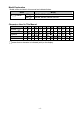
Performance Reference input accuracy (at 23 ) SE2EA and SE1EA: Within 0.1% of each input span R, S inputs -50 to 200 (-58 to 392 ): Within 6 (12 ) B input, 0 to 300 (32 to 572 ): Accuracy is not guaranteed. K, J, E, T, N inputs, Less than 0 (32 ): Within 0.4% of input span SE2RA and SE1RA: Within 0.1% of each input span SE2AA, SE2VA, SE1AA and SE1VA: Within 0.
10. Troubleshooting 10.1 Indication Problem Presumed Cause and Solution The Input display is flashing " " or " ". The input value does not change. • The sensor may be burnt out. Change each sensor. • Check whether the sensor is securely connected to the input terminals of the instrument. Ensure that the sensor terminals are securely connected to the input terminals of the instrument. • Check the input signal source. • Check whether polarity of thermocouple or compensating lead wire is correct.
11. Character Table Alarm Setting Group SE2 A: CH1 and CH2 have respective setting items. Display Setting Item Factory Default Value A1 value 0 (SE2EA, SE2RA, SE1EA, SE1RA) A2 value 0 (SE2AA, SE2VA, SE1AA, SE1VA) A3 value A4 value 0 (SE1EA, SE1RA) A5 value 0 (SE1AA, SE1VA) A6 value Data Function Group SE2 A: CH1 and CH2 have respective setting items.
Display Setting Item A5 HOLD function A6 HOLD function A1 hysteresis A2 hysteresis A3 hysteresis A4 hysteresis A5 hysteresis A6 hysteresis A1 delay time A2 delay time A3 delay time A4 delay time A5 delay time A6 delay time Factory Default Value Data OFF 1.0 (SE2EA, SE2RA, SE1EA, SE1RA) 1.0% (SE2AA, SE2VA, SE1AA, SE1VA) 1.0 (SE1EA, SE1RA) 1.0% (SE1AA, SE1VA) 0 sec Special Function Group SE2 A: Setting items are common to CH1 and CH2.