
User`s manual


Guide Port Cabling
Revision 1.0
Copyright 2005, Shoestring Astronomy
Many telescope mounts are capable of autoguiding, or can be modified to add this capability.
Unfortunately, there is no standardized interface that all manufacturers (or even within a single
manufacturer) use for this function. However, most mounts do use a de-facto standard that for lack of a
better name is referred to as ST-4. This refers to a popular model of autoguider from Santa Barbara
Instrument Group (SBIG), the ST-4.
ST-4 interfaces use a modular-style connector and jack similar to telephone cabling, but they are
different. Telephone cabling is referred to as RJ-11 and it uses four wires, and a six position connector
that only has contacts in the middle four positions. ST-4 style guide ports use a modular cable called
RJ-12 that uses six wires, and a six position connector that has contacts in all six positions.
ST-4 style guide ports (sometimes referred to as autoguide ports or CCD ports) look
like the diagram shown to the right. The pins are connected as:
Pin 1: Usually not connected, but this may be power pin on some mounts
Pin 2: Common (ground)
Pin 3: RA+
Pin 4: Dec+
Pin 5: Dec-
Pin 6: RA-
With RJ-12 cables, the six wires are colored white, black, red, green, yellow, and blue. Because the
cable is flat, the modular connector can be crimped onto the cable in two ways, white to pin one or blue
to pin one. Furthermore, when connectors are placed at both ends of a cable, it can be done with pin 1 to
pin 1, or pin 1 to pin 6.
If you build or buy a cable to work with the Shoestring Astronomy guide port
interface products, you must be absolutely sure that is has pin 1 connected to pin
1, pin 2 to pin 2, etc. Otherwise, you risk the possibility of unpredictable
operation and possibly damage to your mount and your Shoestring adapter.
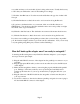
If you build/buy a cable, please make sure that both ends of the cable are wired as
shown in the picture at the right. This view is with the connector lock tab facing away
from you. Note carefully the color and order of the six wires.
Pin 1
Pin 1