READ THIS FIRST Model W1737/W1738 ***IMPORTANT UPDATE*** Applies to Models Mfd. Since 1/14 and Owner's Manual Revised 11/09 Phone #: (360) 734-3482 • Tech Support: tech-support@shopfox.biz • Web: www.shopfox.biz We made the following changes to this machine since the manual was printed: • • • • Obtained CSA certification meeting CSA C22.2 #105-1953 and UL 987-7th standards. Changed contactors, overload relays, and fuses inside electrical cabinet. Changed machine wiring.
Replaces Page 6 Model W1737/W1738 (Mfd. Since 1/14) SAFETY For Your Own Safety, Read Manual Before Operating Machine The purpose of safety symbols is to attract your attention to possible hazardous conditions. This manual uses a series of symbols and signal words intended to convey the level of importance of the safety messages. The progression of symbols is described below.
Model W1737/W1738 (Mfd. Since 1/14) Replaces Page 7 WEARING PROPER APPAREL. Do not wear clothing, apparel, or jewelry that can become entangled in moving parts. Always tie back or cover long hair. Wear non-slip footwear to avoid accidental slips, which could cause loss of workpiece control. FORCING MACHINERY. Do not force machine. It will do the job safer and better at the rate for which it was designed. NEVER STAND ON MACHINE.
Replaces Page 8 Model W1737/W1738 (Mfd. Since 1/14) Additional Safety for Wide Belt Sanders Serious injury or death can occur from hands getting trapped between workpiece and conveyor table, getting entangled in rotating parts inside machine, or lacerated by sanding drum. Workpieces thrown by sander can strike nearby operators. Long-term respiratory damage can occur from using sander without proper use of a respirator and an adequate dust collection system.
Model W1737/W1738 (Mfd. Since 1/14) Replaces Page 10 ELECTRICAL Availability Before installing the machine, consider the availability and proximity of the required power supply circuit. If an existing circuit does not meet the requirements for this machine, a new circuit must be installed. To minimize the risk of electrocution, fire, or equipment damage, installation work and electrical wiring must be done by a qualified electrician in accordance with all applicable codes and standards.
In Addition to Page 10 Model W1737/W1738 (Mfd. Since 1/14) W1737 Circuit Requirements for 230V This machine is prewired to operate on a 230V power supply circuit that has a verified ground and meets the following requirements: Nominal Voltage.......................... 220V, 230V, 240V Cycle.........................................................60 Hz Phase............................................... Single-Phase Circuit Rating..........................................
Model W1737/W1738 (Mfd. Since 1/14) Replaces Page 11 440V Conversion (W1738) This machine is prewired for 230V 3-phase power but has the capability of operating on 460V power with a minor conversion. The conversion consists of replacing two overload relays and rewiring each of the three motors. Transformer All wiring changes must be inspected by a qualified electrician or service personnel before the machine is connected to the power source.
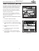
Replaces Page 21 Model W1737/W1738 (Mfd. Since 1/14) Using the Platen The platen controls (Figure 25) on your sander allow for three basic types of sanding. Note: The platen scale is broken down in millimeter increments, and is for only reduced-platen sanding depth positions. For aggressive sanding, retract the platen to the Platen Up position, adjust the table, and let the drums make the deep cut.
Model W1737/W1738 (Mfd.
Replaces Page 36 Model W1737/W1738 (Mfd.
Model W1737/W1738 (Mfd.
Replaces Page 39 Model W1737/W1738 (Mfd.
Model W1737/W1738 (Mfd.
Replaces Page 41 Model W1737/W1738 (Mfd.
Model W1737/W1738 (Mfd.
Replaces Page 43 Model W1737/W1738 (Mfd. Since 1/14) Electrical Parts List REF PART # 1 2V2 X1737001 X1737002V2 2V2 X1738002V2 3V3 X1738003V3 4V2 5V2 5V2 6 7 8 9 10 11 11 12 12-1 14V2 X1737004V2 X1737005V2 X1738005V2 X1737006 X1737007 X1737008 X1737009 X1737010 X1737011 X1738011 X1737012 X1737012-1 X1737014V2 DESCRIPTION REF CURRENT SENSOR CONTACTOR SCHN LC1D50A V2.03.11 (W1737) CONTACTOR SCHN LC1D40A V2.03.11 (W1738) OL RELAY SCHN LRD340 30-40A V3.04.13 (W1738) FUSE 4A 10 X 38MM V2.03.
In Addition to Pages 52–53 Model W1737/W1738 (Mfd. Since 1/14) New Upper Roller Air Cylinder Previous Version Oscillation Diaphragm Assembly (P/N 503) New Version Air Cylinder (P/N 503V2) 503V2 562 567 569 REF PART # 503V2 X1737503V2 513 X1737513 562 X1737562 513 568 DESCRIPTION REF PART # DESCRIPTION OSCILLATION AIR CYLINDER V2.01.
Replaces Page 54 Model W1737/W1738 (Mfd.
Model W1737/W1738 (Mfd.
Replaces Page 56 Model W1737/W1738 (Mfd.
Model W1737/W1738 (Mfd.
MODEL W1737/W1738 37" WIDE-BELT SANDER OWNER'S MANUAL (FOR MODELS MANUFACTURED AFTER 10/09) Phone: 360-734-3482 • On-Line Technical Support: tech-support@shopfox.biz COPYRIGHT © JULY 2005 BY WOODSTOCK INTERNATIONAL, INC. REVISED NOVEMBER, 2009 (JB) #6965CR WARNING: NO PORTION OF THIS MANUAL MAY BE REPRODUCED IN ANY SHAPE OR FORM WITHOUT THE WRITTEN APPROVAL OF WOODSTOCK INTERNATIONAL, INC.
WARNING This manual provides critical safety instructions on the proper setup, operation, maintenance and service of this machine/equipment. Failure to read, understand and follow the instructions given in this manual may result in serious personal injury, including amputation, electrocution or death.
SAFETY ELECTRICAL SET UP OPERATIONS MAINTENANCE SERVICE INTRODUCTION...................................................................................................3 About Your New Sander.................................................................................... 3 Woodstock Technical Support............................................................................. 3 Specifications (W1737 and W1738).......................................................................
INTRODUCTION SAFETY ELECTRICAL SET UP OPERATIONS SERVICE.......................................................................................................... 26 Table Stop Switches ...................................................................................... 26 Brake Service.............................................................................................. 27 Changing V-Belts..........................................................................................
INTRODUCTION About Your New Sander Your new SHOP FOX® Sander has been specially designed to provide many years of trouble-free service. Close attention to detail, ruggedly built parts and a rigid quality control program assure safe and reliable operation. Built for industrial shop use, the 37" wide-belt sander is available as the Model W1737, 10 HP, 220V single-phase unit, and the Model W1738, 15 HP, 220V/440V, three-phase unit.
INTRODUCTION W1737/W1738 Owner's Manual (Mfg. 10/09+) Specifications (W1737 and W1738) W1737 Sanding Motor........................... 10 HP, 220V, Single-Phase, 50A, 1725 RPM, 60 Hz W1737 Conveyor Motor.............................1 HP, 220v, Single-Phase, 7A, 1725 RPM, 60 Hz W1737 Elevation Motor........................ 1⁄3 HP, 220V, Single-Phase, 3.6A, 1725 RPM, 60 Hz W1738 Sanding Motor..................... 15 HP, 220/440V*, 3-Phase, 36/18A, 1725 RPM, 60 Hz W1738 Conveyor Motor...................
INTRODUCTION W1737/W1738 Owner's Manual (Mfg. 10/09+) Controls and Features (W1737/W1738) B A O G C H D I J E K F L M A. B. C. D. E. F. G. H. Three 4" Dust Ports and Adapters Digital Table Height Key Pad Control Panel Digital Amp Draw Meter Table Height Handwheel Emergency Stop Push-Panel Upper Right Access Door Non-Slip Conveyor Belt I. J. K. L. M. N. O.
W1737/W1738 Owner's Manual (Mfg. 10/09+) SAFETY SAFETY FIRST! READ MANUAL BEFORE OPERATING MACHINE. FAILURE TO FOLLOW INSTRUCTIONS BELOW WILL RESULT IN PERSONAL INJURY. Indicates an imminently hazardous situation which, if not avoided, WILL result in death or serious injury. Indicates a potentially hazardous situation which, if not avoided, COULD result in death or serious injury.
W1737/W1738 Owner's Manual (Mfg. 10/09+) 12. Do not force the machine. The machine will do a safer and better job if it does the work. 13. Use the correct tool. Do not force the tool or attachment to do a job for which it was not designed. 15. Remove adjusting keys and wrenches. Before turning the machine on, make a habit of checking that all adjusting keys and wrenches have been removed before turning the machine ON. 16. DO NOT use extension cord.
W1737/W1738 Owner's Manual (Mfg. 10/09+) SAFETY Additional Safety Instructions for Sanders READ and understand this entire instruction manual before using this machine. Serious personal injury may occur if safety and operational information is not understood and followed. DO NOT risk your safety by not reading! USE this and other machinery with caution and respect, and always consider safety first, as it applies to your individual working conditions.
W1737/W1738 Owner's Manual (Mfg. 10/09+) Avoiding Potential Injuries SAFETY Figure 1. Correct body and hand positioning. Figure 2. DO NOT operate without safety glasses/respirator! Figure 4. DO NOT stand behind workpiece! Figure 3. DO NOT operate with side door open! Figure 5.
W1737/W1738 Owner's Manual (Mfg. 10/09+) ELECTRICAL REQUIREMENTS 220V/440V Operation ELECTRICAL The SHOP FOX® Model W1737 has a 10 HP, 220V single-phase sanding motor, a 1 HP, 220V feed motor, and a 1⁄3 HP table lift motor; the Model W1738 has 15 HP, 220V/440V three-phase sanding motor, a 1 HP, 220V/440V feed motor, and a 1⁄4 HP table lift motor. Note: If you do not have three-phase power available to supply the Model W1738, you will have to install a phase converter at the power supply.
W1737/W1738 Owner's Manual (Mfg. 10/09+) 440V Conversion (W1738) To connect this machine to 440V three-phase, you must purchase one LR3D-076 overload relay (Shop Fox PN: X1738003-1) and one LR3D-3322 overload relay (Shop Fox PN: X1738011-1). To wire the W1738 to 440V, do these steps: Disconnect the sander from the power source! 2. Open the electrical box located on the back of the machine. 3.
W1737/W1738 Owner's Manual (Mfg. 10/09+) Unpacking SETUP The Model W1737/W1738 has been carefully packaged for safe transporting. If you notice the machine has been damaged in shipment, contact your machine dealer and the shipping company immediately. NOTICE To gain access to the lag bolts that attach the machine to the shipping pallet, you must temporarily remove both lower side panels.
W1737/W1738 Owner's Manual (Mfg. 10/09+) Machine Placement Floor Load: Your sander weighs 1781 lbs and has a 521⁄8" X 493⁄8" footprint. Some floors may require additional bracing to support both machine and operator. • Working Clearances: Consider existing and anticipated needs, size of material to be processed through the machine, and space for auxiliary stands, work tables or other machinery when establishing a location for your sander.
W1737/W1738 Owner's Manual (Mfg. 10/09+) Air Hose Installation Push your air supply hose onto the air pressure regulator inlet fitting, and clamp it in place with a hose clamp as shown in Figure 10. If you prefer, you can replace the included air nozzle with a 3⁄8" male quick connect air coupling. When the air hose is installed, pull up and rotate the regulator air pressure knob until the gauge reads 70 PSI then push down. DO NOT attempt to regulate the air pressure with the ON/OFF air supply lever.
W1737/W1738 Owner's Manual (Mfg. 10/09+) Breather Pin The Model W1737/W1738 has a breather sealing pin installed in the breather plug for the gear reducer. Remove this pin before using your sander (see Figure 13); otherwise, the gear oil will expand with heat and the seals in the gear reducer may leak due to the pressure build up. You may want to retain this pin if you plan on storing your sander for a long period of time. Remove Breather Pin Dust Collection Figure 13. Breather sealing pin removed.
W1737/W1738 Owner's Manual (Mfg. 10/09+) OPERATIONS Control Panel Below is a summary of your sander control panel and the components that it controls. Use the list with Figure 16 to become familiar with your sander. • Sanding Load Amp Meter: Indicates the current amp load on the sanding motor when a sanding operation is in progress. • Sanding Belt Start and Stop Buttons: Turns the sanding motor ON and OFF if the sander has air pressure and the belt is tensioned.
W1737/W1738 Owner's Manual (Mfg. 10/09+) General Operation Your sander will perform many types of operations that are beyond the scope of this manual. If performed incorrectly, many of these operations can be dangerous or deadly. The instructions in this section are written with the understanding that the operator has the necessary knowledge and skills to operate this machine.
W1737/W1738 Owner's Manual (Mfg. 10/09+) Setting Feed Speed The feed belt motor offers variable speeds from 15 to 49 FPM. Figure 17 points out the variable conveyor feed speed control knob. Speed Indicator To change the feed belt speed do these steps: 1. Start the conveyor. 2. Rotate the control knob to the required conveyor speed as indicated by the speed indicator. Only adjust the speed when the conveyor is operating. Using the Amp Draw Meter Control Knob Figure 17.
W1737/W1738 Owner's Manual (Mfg. 10/09+) Emergency Stop When pushed, the emergency stop plate shown in Figure 19 stops the electricity to the motors and also applies an air-disc brake to stop the sander immediately. To use the emergency stop, do these steps: 1. Push the bottom of the emergency stop plate. 2. Hold the emergency stop plate until the sander has come to a complete stop. KEEP the sanding drum drive belts correctly adjusted.
W1737/W1738 Owner's Manual (Mfg. 10/09+) Basic Sanding To achieve the best sanding results experiment with conveyor feed rate, sanding depth, various grits of sandpaper, and oscillation speed. To sand a workpiece, do these steps: 1. 1. 4. Measure the workpiece and record the thickest spot. With the table already calibrated, turn the sander ON, set the feed rate. Type in the thickness of your workpiece using the numeric key pad (Example: for a 2" thick workpiece type 2.
W1737/W1738 Owner's Manual (Mfg. 10/09+) Using the Platen The platen controls (Figure 25) on your sander allow for three basic types of sanding. Note: The platen scale is broken down in millimeter increments, and is for only reduced-platen sanding depth positions. For aggressive sanding, retract the platen to the Platen Up position, adjust the table, and let the drums make the deep cut.
W1737/W1738 Owner's Manual (Mfg. 10/09+) Belt Tracking The belt tracking knob and lever (Figure 26) stops the belt from tracking off of the drums and shutting down the machine. Your goal is to position the belt tracking lever so the belt tracks in the center of the drums and the left-and-right belt movement takes a similar amount of time. Note: To fine-tune the left-and-right movement you will adjust Belt Oscillation Speed outlined on Page 23.
W1737/W1738 Owner's Manual (Mfg. 10/09+) Belt Oscillation Speed For normal operations, the oscillation speed should be set so that it takes approximately a second or two to complete each direction of travel; however, you can experiment with different speeds to see how the results may affect your finished product. Often, you may find that certain speeds yield better results for different varieties of stock and the feed rates chosen.
W1737/W1738 Owner's Manual (Mfg. 10/09+) MAINTENANCE OFF TURN OFF and LOCK the master power switch when doing maintenance so no power is available to the sander! If you ignore this warning serious electrical shock or accidental start may cause injury or death! Vented Plug with Shipping Pin Removed Filler Plug General Regular maintenance on your Model W1737/W1738 ensures optimum performance. Inspect your machine each time you use it.
W1737/W1738 Owner's Manual (Mfg. 10/09+) Cleaning Belts To increase the working life of your sanding belts, clean them whenever they decrease in performance due to heavy loading. Use a Pro-Stik® Cleaning Pad shown in Figure 32. To clean the belts, simply set your table to the thickness of the cleaning pad, and run the pad through the sander two or three times.
W1737/W1738 Owner's Manual (Mfg. 10/09+) SERVICE OFF TURN OFF and LOCK the master power switch when doing service so no power is available to the sander! If you ignore this warning serious electrical shock or accidental start may cause injury or death! Table Stop Switches The table stop switches prevent the table lift motor from driving the table into the sanding drum. Periodically check and adjust (if required) the table stop switches to protect the conveyor. Up and Down Key Figure 34.
W1737/W1738 Owner's Manual (Mfg. 10/09+) Brake Service Check the brake rotor (shown in Figure 36) regularly to make sure it is clean and the pads are still in good condition (thicker than 1⁄8", see Figure 37). Using the emergency stop system for daily machine shutdown will wear out the sanding belts and the brake pads. Inspect for any grease or oil on the brake rotor as oil reduces emergency braking ability. To clean any lubricants from the rotor, only use automotive brake parts cleaner and a dry rag.
W1737/W1738 Owner's Manual (Mfg. 10/09+) Changing V-Belts Check the V-belts periodically to check for signs of glazing, cracking or fraying. If any of these conditions are present, change both V-belts. Note: If the emergency stop system is used to stop the machine as a normal daily event, the breaking system and belts will prematurely wear and require replacement. When shutting down the machine under non-emergency conditions, use the red OFF push buttons.
W1737/W1738 Owner's Manual (Mfg. 10/09+) V-Belt Tension The sanding motor (Figure 41) and table lift motor (Figure 42) V-belts must be tensioned properly for best performance. No adjustment is necessary for the conveyor motor belt, as it uses a variable width pulley. See Figure 43. Only replace the belt if it becomes frayed, cracked, or glazed. If one belt is bad, always replace both belts as a matched set. Both table lift and sanding motor belts are adjusted the same way.
W1737/W1738 Owner's Manual (Mfg. 10/09+) Table Parallelism NOTICE The table has been adjusted at the factory and should require no further attention. However, we recommend verifying its parallelism with the sanding roller. The corners of the table can be independently adjusted up or down. By disconnecting the chain and turning the pertinent table elevation screw sprocket (Figure 44), table parallelism can be achieved.
W1737/W1738 Owner's Manual (Mfg. 10/09+) Feed Belt Tension and Tracking The feed belt tension and tracking has been set at the factory. However, adjust the feed belt tension and tracking if you notice that your feed belt is slipping or is tracking off center and loading up against the positioning wheels (Figure 46) under the conveyor table, you must . To adjust the feed belt tension and tracking, do these steps: 1.
W1737/W1738 Owner's Manual (Mfg. 10/09+) Belt Tracking Safety Switch Belt tracking safety switches are placed on both sides of the belt to act as emergency machine stops if the belt travels too far to one side during oscillation. See Figure 48. Adjustment Bolt To adjust the belt tracking safety switches, do these steps: 1. TURN OFF and LOCK the master power switch so that no power can go to your sander! 2. Make sure the belt tracking and oscillation is adjusted. 3.
W1737/W1738 Owner's Manual (Mfg. 10/09+) Pressure Rollers The pressure rollers are factory set so they are parallel with each other, parallel with the sanding drum, and parallel with the surface of the conveyor table. Additionally, the front pressure rollers must be set 0.040" below the sanding drum, and the rear rollers set at 0.020" below the sanding drum. When these settings are achieved, the pressure-roller spring tension will be correct. To adjust the pressure rollers, do these steps: 1.
W1737/W1738 Owner's Manual (Mfg. 10/09+) General Motor and Transformer Connection W1737 220V Single-Phase Motor Connection Consult your Electrician if Required. 220V 220V 220V 220V 220V M U2 + V2 U3 1 4 6 SANDING MOTOR ROTATION 2 1 3 M - 1 2 1 3 6 CONVEYOR MOTOR ROTATION 4 M - + 2 3 5 4 1 6 TABLE UP/DOWN MOTOR + 2 3 5 W1738 220V Three-Phase Motor/Transformer Connection 2 3 † † Power Supply Phase Converter Installation Required—Consult your Electrician if Required.
W1737/W1738 Owner's Manual (Mfg.
W1737/W1738 Owner's Manual (Mfg.
W1737/W1738 Owner's Manual (Mfg. 10/09+) W1738 General Wiring Diagram R NOTE: Phase Converter Wild Wire Connects To The T Terminal Only.
Sanding Motor Thermal Protection Breaker Sanding Motor Contactor SERVICE Feed Motor Thermal Protection Breaker Feed Motor Contactor Amp Meter Current Sensor UP/DOWN Table Motor Contactors 220V/440V Three-Phase Power Supply Junction Block Two 4 Amp Fuses Emergency Brake Contactor Control System Stepdown Transformer W1737/W1738 Owner's Manual (Mfg.
A1 13 NO 21 NC 4T2 6 T3 4T2 V 95 6 T3 NC 96 W EMERGENCY BRAKE SOLENOID VALVE U 2 T1 97 NO 98 A2 9 8 10 SERVICE -39- THERMAL OVERLOAD 2 T1 14NO 22 NC SANDING MOTOR CONTACTOR 5 L3 9 3 L2 1L1 5 L3 11 13NO 21 NC 3 L2 4T2 6T3 14NO 22 NC U1 2 T1 95 V1 4T2 NO 98 W1 S 11 T 13 12 U1 V1 W1 A2 6 T3 NC 96 OVERLOAD 2 THERMAL 2 T1 97 A1 CONVEYOR CONTACTOR 1L1 R 5 L3 13NO 21 NC 3 L2 A1 R U2 V2 W2 U2 6T3 22 NC V2 4T2 14NO W2 2 T1 2 T T 17 U2 2 20
Sanding Motor Contactor SERVICE Amp Meter Current Sensor Feed Motor Thermal Protection Breaker Feed Motor Contactor UP/DOWN Table Motor Contactors Emergency Brake Contactor 220V SinglePhase Power Supply Junction Block Two 4 Amp Fuses Sanding Belt Overload Relay W1737/W1738 Owner's Manual (Mfg.
-41- 3 L2 9 5 L3 White S 2 T1 U V 6 T3 SOLENOD VALVE 4 T2 14 NO 22 NC 21 NC 13 NO SANDING BELT CONTACTOR 1L1 R 8 9 SERVICE Red 10 11 8 10 4T2 9 U1 6T3 NC 95 96 NO 97 98 2 T1 4T2 2 T1 14 NO 22 NC A2 6 T3 5 L3 13 NO 21 NC A1 3 L2 CONVEYOR BELT 1L V1 S V2 4T2 U3 6 T3 17 14 NO 22 NC A2 19 V2 2 2 T1 U2 21 5 L3 U3 4T2 11 19 6 T3 12 14NO 22 NC A2 20 13 NO 21 NC A1 1L 3 L2 S R 13 12 U1 V1 U2 V2 U3 16 17 18 19 13 12 11 10 9 U2 2 T1 5 L3 R TABLE UP/
W1737/W1738 Owner's Manual (Mfg.
W1737/W1738 Owner's Manual (Mfg. 10/09+) REF PART # DESCRIPTION REF PART # DESCRIPTION 1 2 X1737001 X1737002 2 X1738002 3 X1737003 3 X1738003 4 5V2 5V2 6 7 8 9 10 11 11 12 X1737004 CURRENT SENSOR CONTACTOR LC1-D50 (W1737 220V 1PH) CONTACTOR LC1-D40 (W1738 220V/440V 3PH) RELAY LR3D-3359 (48-65A) (W1737 220V 1PH) RELAY LR3D-3355 (30-40A) (W1738 220V 3PH) FUSE 4A TERM. BLK. (W1737) V2.10.09 TERM. BLK. (W1738) V2.10.
W1737/W1738 Owner's Manual (Mfg.
W1737/W1738 Owner's Manual (Mfg.
W1737/W1738 Owner's Manual (Mfg.
W1737/W1738 Owner's Manual (Mfg.
W1737/W1738 Owner's Manual (Mfg.
W1737/W1738 Owner's Manual (Mfg.
W1737/W1738 Owner's Manual (Mfg.
W1737/W1738 Owner's Manual (Mfg. 10/09+) REF PART # DESCRIPTION REF PART # DESCRIPTION 400 401 401 401-1 401-2 401-2 401-3 401-3 402 404 405 406 407 409 410 411 412 413 414 415 416 417 418 419 420 421 X1737400 X1738401 X1737401 XPC400C X1738401-2 X1737401-2 X1738401-3 X1737401-3 XPB16 XP2606 XPB07M XPB16 XPB18 XPB32M XPB95 XPK66M XPLW01 XPLW04 XPLW04M XPLW06M XPN02 XPR15M XPS04 XPS10 XPSB16 XPSB62 SPECIAL SCR M8-1.
W1737/W1738 Owner's Manual (Mfg.
W1737/W1738 Owner's Manual (Mfg.
W1737/W1738 Owner's Manual (Mfg.
W1737/W1738 Owner's Manual (Mfg.
W1737/W1738 Owner's Manual (Mfg.
W1737/W1738 Owner's Manual (Mfg.
W1737/W1738 Owner's Manual (Mfg. 10/09+) Safety Label Placement The safety labels on this machine warn and indicate how to protect the operator or bystander from machine hazards. The machine owner MUST maintain the original label location and readability. If a label is removed or becomes unreadable, REPLACE the label before using the machine. For new labels, contact Woodstock International at (360) 734-3482 or www.shopfox.biz.
W1737/W1738 Owner's Manual (Mfg.
W1737/W1738 Owner's Manual (Mfg.
W1737/W1738 Owner's Manual (Mfg. 10/09+) Troubleshooting Symptom Possible Cause How To Remedy Motor will not start; fuses or circuit breakers blow. 1. Low voltage. 2. Open circuit in motor or loose or shorted connections. 3. Short circuit in motor or loose connections. 4. Incorrect fuses or circuit breakers. 5. Faulty start capacitor. 6. Faulty motor. 1. Check power line for proper voltage. 2. Inspect all lead connections on motor for loose, shorted, or open connections and replace or repair. 3.
WXXXX Machine Name Warranty Woodstock International, Inc. warrants all SHOP FOX® machinery to be free of defects from workmanship and materials for a period of two years from the date of original purchase by the original owner. This warranty does not apply to defects due directly or indirectly to misuse, abuse, negligence or accidents, lack of maintenance, or reimbursement of third party expenses incurred. Woodstock International, Inc.
WXXXX Machine Name Warranty Registration Name____________________________________________________________________________________ Street___________________________________________________________________________________ City__________________________ State____________________________Zip_________________________ Phone #_______________________ Email___________________________Invoice #____________________ Model #_________Serial #______________Dealer Name__________________Purchase Date___________ CUT ALONG DO
FOLD ALONG DOTTED LINE Place Stamp Here Woodstock international, inc. p.o.
High Quality Machines and Tools Woodstock International, Inc. carries thousands of products designed to meet the needs of today's woodworkers and metalworkers.