Patented Precision Woodworking Tools The only table saw fence with Automatic Positioning Control™ INCRA TS-III ULTRA OWNER’S MANUAL Please read this manual before use and keep it at hand for easy reference. For many years, INCRA has been the accepted upgrade of choice for thousands of woodworkers seeking to improve the accuracy and repeatability of their wood cutting tools. Today, your search for the perfectly placed cut will come to an end.
SAFETY INSTRUCTIONS Important safety instructions for using the INCRA TS-III Ultra ■ Always keep both hands behind the fence when moving the INCRA TS-III Ultra to a new setting. ■ Before using the INCRA TS-III Ultra, read and follow all of the instructions and safety information in this manual. ■ Before making a cut, always make sure that the carriage clamp is fully engaged. ■ Use appropriate safety devices.
SYSTEM DESCRIPTION 1 Positioning Control 2 3 4 5 6 7 8 9 The INCRA TS-III Ultra obtains its great accuracy and repeatability from the precision cast sawtoothed racks which position the fence in exact increments of 1/32”. Rip Fence The 36” long heavy-duty rip fence is precision machined for perfect flatness along its length. T-slots along the front face permit easy addition of user made wooden subfences using standard ¼-20 hex bolts and hex nuts.
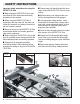
PREPARING YOUR SHOPSMITH WORKSTATION To enjoy the full working range of the INCRA TS-III Ultra , you will want to configure your Shopsmith workstation at shown in Fig. 1. This configuration requires, (2) 5ʼ Connector Tubes, (2) Telescoping Legs, and (2) Floating Tables. The instructions below detail the modifications needed for the floating tables and the final set up. Begin by unplugging the Shopsmith, then remove the blade guard.
3 Add table tab to remaining floating table Mark drill centers on the right edge of the remaining floating table as shown in Fig. 5, then use the (2) #10 x 5/8” self drilling Phillips head fasteners to attach the table tab. See Fig. 6. Leave each of the two fasteners slightly loose to allow the tab to pivot down and out of the way for other floating table applications. For the model 510 floating table, add self adhesive UHMW to both ends of the tubular rails.
INSTALLING THE ULTRA BASE 1 Remove endcap from base support panel Remove the (2) fasteners that secure the endcap to one end of the base support panel and remove the endcap. See Fig. 9. 2 Position the Ultraʼs base on the base support panel as shown in Fig. 11. (Edge of the Ultra base should be about 3 ¼” from the end of the panel.) Use a square to align the Ultra base at 90˚ to the panel and tighten only the four screws installed in the slotted holes.
FENCE ASSEMBLY 1 Slide carriage into Ultra base Figure 13 Slide the carriage into the Ultraʼs base and position the fence mounting bracket above the right edge of the worktable. Pull the carriage clamp up to lock the carriage in place. See Fig. 13. 2 Fence mounting bracket Align fence mounting bracket above edge of worktable and lock carriage clamp Loosely attach rip fence Open hardware pack B-08.
3 Attach fence glides Note: The fence glides included in hardware pack B-08 are configured for the Shopsmith model 520. To convert the glide for the model 510, see the bottom of this page. Place one of the supplied ¾” x 3” cardboard spacers under each end of the fence as shown in Fig. 16 and attach the two fence glides to the rear of the fence using (4) ¼-20 x ½” socket head cap screws, ¼” washers and ¼-20 square nuts. Capture the nuts in the lower T-slot on the fence. See Fig. 17.
FINAL CALIBRATION Align fence parallel to miter slot and tighten Ultra base mounting screws 1 Unlock the carriage clamp, then slide the fence up to the nearest miter slot and clamp in place. Loosen the (4) Phillips head screws that secure the Ultra base to the base support panel and align the fence to the miter slot. See Fig. 19. Retighten the (4) screws.
3 Set scale position Figure 21 With the Ultra base still locked with the rip fence at the “zeroed” position set in step 2, lift one end of the stainless steel scale from the magnetic track and slide the scale to position 0” under the hairline cursor. See Fig. 21. Lower the scale back onto the magnetic track. If you want, you can also slide the two-piece lexan scale to agree with the stainless steel scale. Make sure the overlapping ends of the scales are aligned at 16”.
movement easy. Just rotate the tab up. As the rip fence is moved off of the worktable onto the floating table it contacts the table tab and, as movement is continued, the floating table moves with the rip fence. See Fig 24. When moving the rip fence back to the worktable, just grasp the rip fence and the table tab together and the floating table moves forward with the fence. Let go of the tab when you reach the worktable. A little paste wax on your extension tubes will allow the floating table to move easily.
when cutting grooves to accept inlay strips for a flawless fit, or to loosen up a tight fitting joint. Youʼll find it extremely useful when “zeroing” to the fence to the bit or blade or for “centering” the cutter on your work piece when setting up for joinery operations. Letʼs use a “hands on” step-by-step approach for getting acquainted with, and using the various components of this important feature.
can micro adjust a full 1/4” in either direction. The scale is marked in 1/32” increments. IMPORTANT: Do not turn the micro adjusting knob with the carriage clamp in the “locked” position. The carriage clamp must always be “unlocked” and the micro adjust lever pushed down before micro adjusting the fence position. TIP ▼▼▼▼▼▼▼▼▼▼▼ At the end of each day, you might want to micro adjust back to midrange on the range scale.
Realigning the micro adjust range scale If you wish to verify the mid-range location of the microadjust range scale use the following procedure: “Unlock” the carriage clamp and press the micro adjust lever down to place the Ultra base in the micro adjust mode. Turn the micro adjust knob clockwise until there is noticeable resistance to the rotation of the knob. DO NOT force the knob.
Now locate the carriage so that the Ultra base is centered approximately between the ends of racks #2 and #3. Again, lock the carriage clamp to bridge the two racks and tighten the accessible mounting screw on rack #3. Then unlock the carriage and move forward to tighten the remaining screw on rack #3. Continue this “bridge and tighten” procedure for the remaining racks on the carriage. this particular condition is really quite simple.
This page is intentionally blank.