
Installation guide

ShoreTel 60 Voice Switch ShoreTel Voice Switches
F
ShoreTel 14.2 Planning and Installation Guide 479
ShoreTel 40 Voice Switch
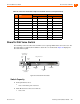
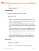
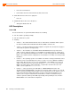
The following sections describe ShoreTel 40 resource capacity, LED behavior, and connectors. The
ShoreTel 40 is not supported in installations outside the U.S. and Canada. Figure 95 displays the
ShoreTel 40 front plate.
The ShoreTel 40 is often referred to as the ShoreTel 40/8 (SG 40/8).
Figure 95: ShoreTel 40 Front Plate
Switch Capacity
Analog Circuit Resources
Ports 1-2: Two Loop Start Trunks, DID Trunks, or Extensions
Ports 3-4: Two Loop Start Trunks.
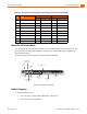
– 17 Orange/Yellow 42 Yellow/Orange
– 18 Green/Yellow 43 Yellow/Green
– 19 Brown/Yellow 44 Yellow/Brown
– 20 Slate/Yellow 45 Yellow/Slate
– 21 Blue/Violet 46 Violet/Blue
– 22 Orange/Violet 47 Violet/Orange
– 23 Green/Violet 48 Violet/Green
– 24 Brown/Violet 49 Violet/Brown
– 25 Slate/Violet 50 Violet/Slate
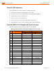
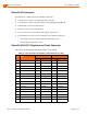
Table 95: ShoreTel 60 RJ-21X Telephone and Trunk Connector Pins(Continued)
Port Type
Ring Tip
Pin # Cable Color Pin # Cable Color
ShoreGear
-
40/8
Default
Switch
Audio Output Port
(night bell)
Power
LED
RS-232C
Maintentance
Port
RJ-21X Telco
Port
Audio Input Port
(music on hold)
Network
LEDs
LAN
Connectors
Analog Phone RJ-11
Switch Port
LEDs