
Installation guide

482 Planning and Installation Guide ShoreTel 14.2
ShoreTel Voice Switches ShoreTel 60 Voice Switch
F
This LED is not directly related to any switch’s individual network activity. For example, if three
switches are connected to the same hub and one switch’s Traffic LED shows activity, the other
switches will indicate the same activity.
100M
When green, the switch is connected to a 100BaseT network.
When off, the switch is connected to a 10BaseT network.
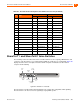
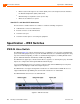
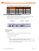
ShoreTel 40 Connectors
The ShoreTel 40 voice switch contains the following components:
1 3.5 mm mono connector for audio input (music on hold)
1 3.5 mm mono connector for audio output (overhead paging and night bell)
1 DB-9 female connector for maintenance
2 RJ-45 connectors for the LAN interface
1 RJ-11 connector for connecting an analog phone (extension 9)
1 RJ-21X male connector for mass termination of the telephone/trunk ports
Power Failure Transfer Unit: Trunk Port 4 to Extension Port 5
Backup Operator: Extension Port 5
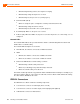
ShoreTel 40 RJ-21X Telephone and Trunk Connector
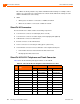
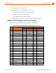
Table 96 lists the RJ-21X Ring and Tip pin numbers for the SG 40I.
Table 96: ShoreTel 40 RJ-21X Telephone and Trunk Connector Pins
Port Type
Ring Tip
Pin # Cable Color Pin # Cable Color
– 1 Blue/White 26 White/Blue
– 2 Orange/White 27 White/Orange
– 3 Green/White 28 White/Green
– 4 Brown/White 29 White/Brown
1 Trunk, DID, Extension 5 Slate/White 30 White/Slate
2 Trunk, DID, Extension 6 Blue/Red 31 Red/Blue
3 Trunk 7 Orange/Red 32 Red/Orange
4 Trunk 8 Green/Red 33 Red/Green
5 Extension 9 Brown/Red 34 Red/Brown
6 Extension 10 Slate/Red 35 Red/Slate