
Installation guide

490 Planning and Installation Guide ShoreTel 14.2
ShoreTel Voice Switches IPBX-T1 and IPBX-E1 Voice Switch
F
IPBX-T1 and IPBX-E1 Voice Switch
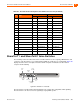
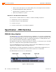
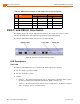
The IPBX-T1 (Figure 98) provides higher-density trunking to the central office using T1 or PRI
signaling. The IPBX-E1 provides higher-density trunking using E1 PRI signaling.
The IPBX-T1 and IPBX-E1 LEDs and connectors are defined below.
Figure 98: ShoreTel T1 and ShoreTel E1 Front Panel
LED Descriptions
Power LED
The IPBX-T1 and IPBX-E1 have one red power LED, which indicates the following:
On: The switch is operating normally.
Off: The switch has no power.
Flashing
2 flashes — The switch failed its internal self-test. This indicates a hardware failure; replace
the unit and submit a Return Material Authorization (RMA) to ShoreTel, Inc.
3 flashes — Booting via FTP. Flash memory may be corrupted. Go to the Quick Look page to
make sure that the system is running properly.
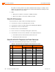
22 Extension 22 Orange/Violet 47 Violet/Orange
23 Extension 23 Green/Violet 48 Violet/Green
24 Extension 24 Brown/Violet 49 Violet/Brown
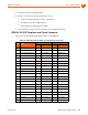
– 25 Slate/Violet 50 Violet/Slate
Table 97: IPBX-24 RJ-21X Telephone and Trunk Connector Pins(Continued)
Port Type
Ring Tip
Pin # Cable Color Pin # Cable Color