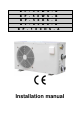
B P - 3 5 W S - B B P - 5 0 W S - B B P - 5 0 H S - A B P - 8 5 H S - A B P - 1 0 0 H S - A Installation manual
E N G L I S H 1. General warnings and information for the addressee. 1.1. CE declaration. Business name: Shott International S.r.l. Via delle Pezze, 35 35013 CITTADELLA (PD) - ITALY Tel. +39 049-9401150 Fax. +39 049-9409140 C.F. 03529990289– P.IVA 03529990289 Cap. Soc. € 250.000,00 i.v. – R.E.A. n. 317778 Iscritta al n. 03529990289 Reg. Imprese di Padova e-mail: infos@shott.it http:\\www.shott.
E N G L I S H 1.2. Warranty. 1.2.1. General conditions. i. In accordance with these provisions, the dealer guarantees that the Product under this warranty (“the Product”) does not have any conformity defect upon delivery. ii. The Product Warranty Period is two (2) years, effective upon delivery to the purchaser. iii.
E N G L I S H 1.3. Symbol key. Indicates hazardous situations and warnings. The manual parts marked by this symbol must be read with the utmost care. Indicates that work must not be performed on live electrical equipment. This work can begin after taking safety measures1. 1.4. Safety regulations for heated pools2. During normal swimming activities, 26÷30 [°C] water temperature is recommended. 38 [°C] water temperature is only considered safe for adults in good health conditions.
E N G L I S H SERIES BP heat pumps must not be used with other heating systems such as electric heaters. This manual provides instructions for the installation and use of SERIES BP heat pumps. Carefully read this manual before installation. Failure to observe the manual instructions may cause personal or property damages or damage the heat pump. Failure to observe the instructions in this manual immediately null and voids the warranty.
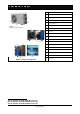
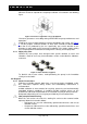
E N G L I S H 2.2. Composition. 1 Fan protection net 2 Body 3 display 4 Refrigerant charge valve 5 Pressure manometer 6 Water outlet 7 Power cord 8 Water inlet 9 Heat exchanger 10 Fan 11 Compressor 12 Pressure sensor 13 Heat exchanger 14 Water sensor 15 Four way valve7 16 Ambient sensor8 17 Plate heat exchanger temperature sensor9 18 Flow sensor Figure 1: main heat pump parts. 7 Not included in model BP-xxWS-B (xx=35, 50). Not included in model BP-xxWS-B (xx=35, 50).
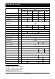
E N G L I S H 3. Technical specifications. Model Unit of measure 10 Thermal power (heating) [kW] Refrigerant power (cooling) [kW] Absorbed power 12 13 Absorbed current 14 BP-35WS-B BP-50WS-B BP-50HS-A BP-85HS-A BP-100HS-A 3.5 5.0 5.0 8.5 10.5 4.3 6.8 8.5 - 11 [kW] 0.7 1.0 1.0 1.7 2.1 [A] 3.5 5.5 5.5 7.9 9.8 4.2 5.0 5.0 3.6 4.0 4.
E N G L I S H 4. Installation. The heat pump must be installed and commissioned by specialised technicians and in keeping with current national system regulations. Installation must be conducted evaluating all the specific site factors: vicinity and height of walls, public accessibility, etc. 4.1. Inspection. Upon receiving the heat pump, check packaging integrity. The machine should come with complete manuals, for the user and for installation. 4.2. Handling.
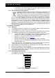
E N G L I S H 4.3.2. Necessary clearance. Minimum clearance required for heat pump installation is illustrated in the following figure. Figure 2: Clearance required for correct installation. Clearance guarantees accessibility during SERIES BP heat pump maintenance and operations. Avoid hot air from circulating between machine distribution and suction. See Figure 2. For this purpose, avoid all situations in which there could be an obstacle to the free flow of air produced by the fan.
E N G L I S H The body and various parts, if unusable, should be dismantled and divided according to their material type (for example, copper, aluminium, plastic, etc.) and must be sent to collection centres. 4.4.3. Electric/electronic waste disposal. In keeping “Implementation of Directives 2002/95/CE, 2002/96/CE and 2003/108/CE” on the reduction of the use of hazardous substances in electric and electronic material as well as waste disposal.
E N G L I S H The pump must be hydraulically connected with PVC tubes with 50 [mm] external diameters.Tubes must be inserted in the fittings for about 1÷2 [cm] and secured with the supplied fast connections. Output fitting Input fitting Figure 5: Hydraulic connections The hydraulic circuit is usually created as illustrated in the following figure. Figure 6: Typical hydraulic circuit part layout. Minimum heat pump water input flow must not be under the value required for the model in question.
E N G L I S H Figure 7: Protection device and/or contact switch. The electrical mains connected to the heat pump must be grounded. If a socket is installed for electrical mains connections, the latter must have a protection grade no lower than IPX4 and must have a grounding terminal. The same applies for the mains which must be grounded. 4.7. Socket installation for mains connections.
E N G L I S H Model BP-xxHS-A (xx=50, 85, 100) Model BP-xxWS-B (xx=35, 50). Figure 10: Wiring diagram. YV FM CM PCB LDB-1 XT1 XT2 C1 C2 Four way valve Fan motor Compressor Control board Dispersion sensor Electrical mains connection terminals Hub Compressor capacitor Fan capacitor Table 1: Control board part legend. Nome file: 7500016 - ISTR.INSTALL. HEAT PUMP VERS. EN.doc Page 13-di/of 40 Rev.
E N G L I S H 4.9. Commissioning, preliminary checks. 4.9.1. Commissioning, precautions. Before starting the pump, make sure there is water in the pool, that the skimmer and suction fittings, when installed, are submerged, that the cut-off valves do not prevent water flow from the pool to the heat pump and vice versa and that the circulation pump is on. 4.9.2. First start-up, preliminary checks.
E N G L I S H 5. Operations and use. 5.1. Introduction. Please read the paragraph on energy savings, see Paragraph 1.5. SERIES BP heat pumps are equipped with control boards which, thanks to a simple but functional interface, allow heat pump programming to guarantee efficient service. Figure 11: Heat pump panel. Heat pump on/off button. Operating mode selection button (heating/cooling18) or operating parameter programming access. Up button. Down button. Multi-function button.
E N G L I S H 5.2.4. Starting the heat pump. . The heat pump starts within 3 minutes. The last To start the heat pump, press selected operating mode (heating or cooling20), see Figure 13. Figure 14 and Paragraph 5.2.13.8, the last temperature set and the current pool water temperature (heating or cooling) is immediately displayed. Heating mode Set temperature Current pool water temperature Figure 13: Heat pump display when turned on, heating mode.
E N G L I S H restart temperature are a –15 [°C] and –13 [°C] respectively, minimum admissible values. The minimum working temperature must be at least 2 [°C] lower than the restart temperature. Proceed as follows to set minimum working temperature: o When the pump is in standby, see Paragraph 5.2.2, press and hold down for 3 seconds. Minimum working temperature Restart temperature Figure 15: Minimum working temperature and restart temperature.
E N G L I S H 5.2.10. Manual defrost23. Frost may form on the plate heat exchanger during normal operations in heating mode, see Figure 1. Frost on the plate heat exchanger reduces heat pump performance. Frost is formed during heating mode because the heat pump cools surrounding ambient air to heat water. SERIES BP pumps are equipped with a temperature sensor that detects frost on the plate heat exchanger and starts automatic defrost. However, if this is insufficient, manual defrost can be started.
E N G L I S H The temperature read by each sensor can be displayed by pressing (for model ) and hold down for 3 seconds with the pump is BP-xxWS-B (xx=35, 50), press running, see Paragraph 5.2.4. To display temperatures read by the various sensors, press (for model BP-xxWS-B (xx=35, 50), press ). The temperature read by the sensor is displayed for 10 seconds, if no other key is pressed, or to return usual information to the display, see Figure 13 and Figure 14.
E N G L I S H key is pressed within 10 seconds or if is pressed, usual standby mode information is displayed, see Paragraph 5.2.2. Each parameter is marked by an identification number. The following table lists for each parameter: • Identification number • Description. • Admissible value range. • Default settings (set at heat pump assembly). Parameter identification number Parameter value Figure 26: Parameter programming.
E N G L I S H 5.2.13.1. Pool temperature regulation range28. Parameter 0 sets the water temperature regulation range. One of the following two ranges can be selected: 0. 5÷45 [°C]; 1. 5÷60 [°C]. With default settings, pool temperature can be regulated in the range 5÷45 [°C]. For further information, see Paragraph 1.4. Do not change this parameter. Figure 27: Parameter 0 settings, default settings. 5.2.13.2. Automatic defrost start temperature29.
E N G L I S H 5.2.13.4. Automatic defrost repetition time31. Parameter 3 is used to select when the automatic defrost process is started. The value can be selected in range 10÷150 minutes. Default settings are 150 minutes (F0). The minimum increase or decrease of this parameter can be 10 minutes. This parameter can be changed according to ambient conditions. Reducing the automatic defrost process in very cold countries (i.e.: Northern Europe) is recommended, 120 minutes (C0).
E N G L I S H 5.2.13.7. Automatic restart. Following a black out, the parameter enables automatic restart of the operating mode prior to the black out. Example: When parameter 8 (Parameter 2 for model BP-xxWS-B (xx=35, 50)) is 1, when a black out occurs with the heat pump running, see Paragraph 5.2.4, the heat pump automatically restarts when power returns. Vice versa, when parameter 8 (Parameter 2 for model BP-xxWS-B (xx=35, 50)) is 0, the heat pump is in standby when power returns, see Paragraph 5.2.2.
E N G L I S H parameter settings were selected to guarantee maximum comfort and minimum energy consumption. BP-xxHS-A (xx=35, 50) models. BP-xxWS-B (xx=35, 50) model. Figure 35: Parameter 10 settings (0 parameter for model BP-xxWS-B (xx=35, 50)), default settings. 5.2.13.10. Control mode34. Parameter 11 is used to select one of the two control modes35: 0. heat pump; 1. heater. Heat pump operations are default settings. Do not change this parameter. Figure 36: Parameter 11 settings, default settings. 5.
E N G L I S H Figure 37: Ambient temperature sensor. Figure 38: Pool water temperature sensor. Temperature sensors are connected to connector CN4 (ambient temperature and water temperature) as indicated in the wiring diagram, see Figure 10. Sensor operations can be checked by measuring the resistance when temperature changes. Usual values are indicated in Paragraph 6.3. 6.1.2. Flow sensor. SERIES BP control pumps are equipped with a flow sensor that continuously reads water flow.
E N G L I S H 6.2.3. Low pressure sensor. The low pressure sensor stops the compressor when suction pressure in the high pressure section is under the calibration value. Trigger pressure is 0.05 [bar]. After a low pressure alarm, the heat pump must be manually restarted, see Paragraph 5.2.4. Figure 42: High pressure sensor. Nome file: 7500016 - ISTR.INSTALL. HEAT PUMP VERS. EN.doc Page 26-di/of 40 Figure 43: Low pressure sensor. Rev.
E N G L I S H 6.3. Pool, ambient and plate heat exchanger temperature sensor resistance values. Table 3: Pool, ambient and plate heat exchanger temperature sensor resistance values. Nome file: 7500016 - ISTR.INSTALL. HEAT PUMP VERS. EN.doc Page 27-di/of 40 Rev.
E N G L I S H 6.4. Compressor temperature sensor resistance values Table 4: Compressor temperature sensor resistance values. Nome file: 7500016 - ISTR.INSTALL. HEAT PUMP VERS. EN.doc Page 28-di/of 40 Rev.
E N G L I S H 7. Routine, scheduled and extraordinary maintenance. Periodic controls are required to keep SERIES BP heat pumps in good working order and to guarantee the foreseen performance and safety levels. Some controls can be performed by the user while specialised technicians are required for others. During normal operations, the heat pump plate heat exchanger produces condensation. The amount of condensation produced varies according to ambient conditions.
E N G L I S H - turn off the heat pump, see Paragraph 5.2.3; turn on the heat pump, see Paragraph 5.2.1; start the heat pump, see Paragraph 5.2.4. Problem The heat pump does not turn on, see Paragraph 5.2.1. The heat pump does not start, see Paragraph 5.2.6. Possible cause The instructions in Paragraph 5.2.1 were not followed. The mains connection line protection device fuse is burned out or the contact switch triggered, see Paragraph 4.6. The 3 minutes required for pump start have not elapsed.
E N G L I S H Problem Possible cause Probable accumulation of condensation. See Paragraph 4.3. Water leaks from the heat pump. Error message EE b is displayed. Error message EE c is displayed. Error message EE d is displayed. The heat pump does not 38 work and error message EE 1 is displayed. The heat pump does not 39 work and error message EE 2 is displayed. The heat pump is running 40 work and error message EE 3 is displayed. 41 The heat pump is running and error message EE 4 is displayed.
E N G L I S H Problem st Possible cause 1 solution Compressor temperature too high. Wait until compressor temperature drops. Refrigerant circuit leak . Check for leaks with a leak detector and replace defective refrigerant circuit parts. Capillary circuit clogged Replace the capillary circuit. The heat pump does not 45 work and error message EE 7 is displayed. Current dispersion Replace the defective component: Compressor, fan, four way valve, electronic board.
E N G L I S H BP-xxHS-A (xx=50, 85, 100) models. 8. Spare parts. Figure 44: Spare parts details. Nr. 1 2 3 4 5 6 7 8 9 10 11 12 13 14 15 16 17 18 19 20 21 22 23 Description.
BP-xxWS-B (xx=35, 50) model. E N G L I S H Figure 45: Spare parts details. Nr. 1 2 3 4 5 6 7 8 9 10 11 12 13 14 15 16 17 18 19 20 21 Description. Fan protection net Front panel Control panel cover Control panel Verge board polyfoam Verge board Exhaust pipe Compressor High pressure sensorr Low pressure sensor Flow sensor Gas returning pipe Heat exchanger Rubber water fender Right side board Power cord Right rear board Refrigerant charge valve Pressure manometer Fast connection Gasket Nr.
E N G L I S H 8.1. Special notes on part replacement. 8.1.1. Manometer replacement. Before replacing the manometer, close the valve upstream from the manometer. Valve to be closed Figure 46: Manometer replacement. 8.1.2. Pressure sensor replacement. Use blow torch for pressure sensor replacement. Figure 47: High pressure sensor. Figure 48: Low pressure sensor. 8.1.3. Filter and capillary replacement. The filter and capillary must be replaced using a blow torch.
E N G L I S H Contents. 1. 2. 3. 4. 5. General warnings and information for the addressee........................................................ 2 1.1. CE declaration................................................................................................................. 2 1.2. Warranty.......................................................................................................................... 3 1.2.1. General conditions. .............................................................
E N G L I S H 5.2.13.4. Automatic defrost repetition time. ................................................................... 22 5.2.13.5. Defrost duration. ............................................................................................ 22 5.2.13.6. Compressor protection temperature............................................................... 22 5.2.13.7. Automatic restart............................................................................................ 23 5.2.13.8. Operating mode.
E N G L I S H Nome file: 7500016 - ISTR.INSTALL. HEAT PUMP VERS. EN.doc Page 38-di/of 40 Rev.
E N G L I S H Nome file: 7500016 - ISTR.INSTALL. HEAT PUMP VERS. EN.doc Page 39-di/of 40 Rev.
Nome file: 7500016 - ISTR.INSTALL. HEAT PUMP VERS. EN.doc Page 40-di/of 40 Rev.