
User's Manual


A120S In-Line Switch User Guide
27C8064 (Rev. 5) Printed in U.S.A.
©2005, Shure Incorporated
GENERAL
The A120S Accessory in-Line Switch can be used to add an
On/OFF, Push-To-Talk, Cough Button, or Transmitter-Relay
Keying function to a microphone or other device rated at up
to 3 amps ac (0.5 Adc) 125V, non-inductive load. The switch
has gold-plated contacts for reliable performance even in
low-current circuits. The switch is a double-pole double-
throw type for maximum versatility. Its push button combines
with a rotary knob to provide either spring-return momentary
or locking action.
The unit is supplied with a crimp-on strain relief tor 6.4mm
(0.25-in.) diameter cable and with a flex relief for either large
or small diameter cables. The permanently attached belt clip
can be rotated on the case to any of four positions for the
most convenience in use.
OPERATION
Switch Function Rotary Knob Position
On/Off (Button remains down
until depressed a second time)
Push-To-Talk (Button remains
down only while depressed)
Locking
Momentary
Locking the Switch Button Down
The switch button can be locked down by following these
steps:
Turn the rotary knob to Locking.
Press the switch button down.
Turn the knob to Momentary.
The button will remain locked down until the knob is returned
to locking and the button is depressed again.
SWITCH INSTALLATION AND WIRING
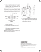
For thicker cable (e.g., one 6.4 mm [0.25 in.] diameter
cable or two 3.8 mm [0.15 in.] diameter cables), cut
off the bottom of the flex relief at the rib. For narrower
cable (e.g., one 2.3 mm [0.39 in.] diameter cable),
use the entire flex relief as supplied. Thread the cable
(s) through the flex relief.
1.
2.
3.
1.
THICKER OR MULTIPLE
CABLES
SINGLE NARROWER
CABLE
FLEX RELIEF
FIGURE 1
For one 6.4 mm diameter cable (0.25 in.), crimp the
strain relief to the cable making sure the eyelet is to-
ward the raw end of the cable. Leave enough raw
cable above the strain relief to permit soldering the
individual conductors to the switch terminals.
NOTE: For all other cables, loosely knot the cable above
the flex relief to form a strain relief. Leave enough raw
cable above the knot to permit soldering the individual
conductors to the switch terminals.
KNOTTED STRAIN RELIEF
6.4 mm (0.25 in.) CABL
E
STRAIN RELIEF FOR ONE
FOR OTHER CABLES
FIGURE 2
2.