
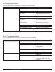
System information


Step 3 (Receiver 1)
Check that the receiver 1 is plugged in, and that both power switches are ON
The RF cascade ports will not pass the RF signal if the receiver 1 is off.
Check the frequency band of receiver 1
It should match the frequency band of receiver 2 since you’re using the RF cascade port to feed the receiver 2.
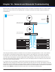
Step 4 (RF Cables)
Check the RF cable connections to the receiver 1
The input cables should be securely plugged into the top BNC input jacks; they should NOT be plugged into either the
bottom BNC cascade jacks or the AES3 word clock jacks.
Check the RF cable connectors
Unplug the cables from both ends and inspect the connector and center pins to ensure they are not missing or damaged.
Check the RF cable connections to the antenna distribution amplifier
The cables should be securely plugged into the RF output BNC jacks. Ensure both RF cables are plugged into both chan-
nel A and channel B RF BNC jacks from the antenna distribution amplifier.
If all of the above steps are completed with no problems found, proceed to Step 5.
Step 5 (Antenna Distribution Amplifier)
Check that the antenna distribution amplifier is plugged in, and that both power switches are ON
The Axient products have two power switches, an AC mains switch on the rear of the unit and a standby switch on the
front. The RF cascade ports will not pass the RF signal if the antenna distribution amplifier is off.
Check the frequency band of the antenna distribution amplifier
The frequency band of the distribution amplifier must either be set to ‘WIDEBAND’ or the frequency band of the micro-
phone receiver.
Check the RF cascade setting (if the receiver is connected to the cascade output)
Make sure that the RF cascade setting is Auto or On.
Check the RF Gain setting
The RF Gain may be set too low. The default setting for the RF gain is 0 dB.
Note: If you’re using the transmitter a long distance from the receiver, adjust the RF Gain control for optimal RF LEDs on the receiver.
If all of the above steps are completed with no problems found, proceed to Step 6.
Note: The linking, channel name, or ShowLink settings of receiver 1 have no effect on the RF cascade output.
If all of the above steps are completed with no problems found, proceed to Step 4.
112
Part 4: Troubleshooting