
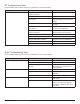
System information


Step 10 (Transmitter)
Check the transmitter power and battery
Ensure the transmitter is powered on and the battery is charged and properly seated in the transmitter.
Check the RF MUTE setting
If the transmitter is RF MUTED, the LCD display will alternately flash ‘RF Muted’ and the set frequency.
Check the frequency of the transmitter against the receiver
The transmitter and receiver frequencies as well as the frequency band must exactly match.
Check the audio gain setting
The transmitter audio gain has up to 50dB of adjustable gain. Adjust the gain level up while monitoring the LCD display
until it reads ‘Input Overload’ for very loud input signals into the microphone.
If all of the above steps are completed with no problems found, proceed to Step 11.
Step 11 (Microphone)
Inspect the microphone connector to ensure the center pins are not damaged, bent or missing. Inspect the cable to en-
sure there are no slices, tears or frayed shields.
If all of the above steps are completed with no problems found, proceed to Step 12.
Step 12 Receiver Audio cables
The usual indicator of an audio problem is the audio LEDs on the receiver are not on or the audio LEDs on the mixing
console are not on. If the audio LEDs on the receiver are all on, that usually means the audio and RF link are working.
Check the audio cable connections out of the receiver
The audio cable should either be securely plugged into the XLR or ¼” output for analog and the AES3 for digital audio
output.
Caution: The same connector type (XLR) is used for both the XLR analog out and the AES3 digital out. Check to see that the audio cable is con-
nected to the right jack for your application and into the proper receiver channel (A or B).
If all of the above steps are completed with no problems found, proceed to Step 13.
114
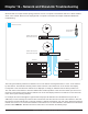
Part 4: Troubleshooting