
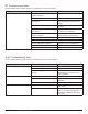
System information


118
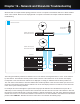
Part 4: Troubleshooting
Step 1 (Receivers)
For this example, we’ll start at the receivers for our troubleshooting method.
Check that the receivers are plugged in, and that both power switches are ON
The Axient products have two power switches, an AC mains switch on the rear of the unit and a standby switch on the
front.
Check the FIND ALL status at the receiver
The FIND ALL function from the Util > Network > Find All menu will query any other Axient devices on the network and
ask for their model number and address properties. The FIND ALL function from the receiver will see other receivers,
ShowLink access points, transmitters (via the ShowLink network), antenna distribution amplifiers, and chargers. The
FIND ALL function will not see the AXT620 Ethernet switch. The FIND ALL device count should match the number of
devices listed above that are connected to the network. If the FIND ALL function returns the correct number of devices, it’s
likely the network is set up and functioning properly.
Check network address settings
The default network address settings for Axient devices are IP address mode = AUTOMATIC (get address from DHCP
server). Assuming a DHCP address server is present and operating on the network, these are the proper IP address
settings for the receiver. Typically, when using a DHCP server on the network, the receiver address mode should NOT be
set to MANUAL.
Check the network port LEDs
The LEDs on the network jack should normally be on and one of them blinking if a physical connection exists from the
receiver to the Ethernet switch 2. If the LEDs are not on, ensure the network cable is securely plugged into the jack. It
doesn’t matter which network jack the cable is plugged into (upper or lower).
If all of the above steps are completed with no problems found, proceed to Step 2.
Step 2 (Receiver Cables)
Check the network cable
If the LEDs are not on at the network jack, check the cable connector for damage to the pins or broken or frayed
connections on the cable. Ensure the cable is securely plugged into both the receiver and the Ethernet switch 2. Try a
replacement cable if you suspect a problem with the cable.
If all of the above steps are completed with no problems found, proceed to Step 3.
Step 3 (Ethernet switch 2)
Check that the Ethernet switch is plugged in
There is no power switch on the Ethernet switch. When the unit is powered on the LED on the front panel will be on.
Check that the DHCP switch on Ethernet switch 2 is OFF
In this example the Ethernet switch 2 is being used to expand the physical network and not as a DHCP server. If two
DHCP servers are active on the same physical network, problems will occur with the IP addresses and other functions of
the receivers.
Note: If the DHCP switch is ON at Ethernet switch 2, switch it to the OFF position, AC power off ALL units on the network and restart the DHCP
server first, and then the rest of the devices.
If all of the above steps are completed with no problems found, proceed to Step 4.