
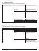
System information


119
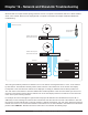
Chapter 19 ‒ Network and ShowLink Troubleshooting
Step 4 (Ethernet Switch 2 Cables)
Check the network cable
If the LEDs are not on at the network jack, check the cable connector for damage to the pins or broken or frayed
connections on the cable. Ensure the cable is securely plugged into both the Ethernet switch 2 and Ethernet switch 1. Try
a replacement cable if you suspect a problem with the cable.
If all of the above steps are completed with no problems found, proceed to Step 5.
Step 5 (Ethernet switch 1)
Check that the Ethernet switch is plugged in
There is no power switch on the Ethernet switch. When the unit is powered on the LED on the front panel will be on.
Check that the DHCP switch on Ethernet switch 1 is ON
If the DHCP switch is off at Ethernet switch 1, switch it to the ON position, AC power off ALL units on the network and
restart the DHCP server first, and then the rest of the devices.
Step 6 (ShowLink Network Troubleshooting)
The typical symptom of ShowLink problems is that the Tx > Adjust menu does not appear on the receiver menu that
you’re trying to adjust the transmitter from. So before we get to the troubleshooting details, let’s review the requirements
to enable remote control.
Requirements for transmitter remote control over the ShowLink network:
1. Have the following Axient components at a minimum and configured for networked operation: AXT100 or AXT200,
AXT400, AXT610.
2. The AXT610 Access Point must be on the same Ethernet network as the AXT400 Receiver.
3. The AXT100 or AXT200 must be IR synced (and linked) to the receiver.
4. Have the AXT100 or AXT200 within the range of the AXT610 Access Point
Check the link status on the receiver
The most likely problems with not being able to remote control a transmitter from the receiver is that either they are not
linked together via an IR sync or the ShowLink access point is not on the network.
When a transmitter is linked to a receiver, the link icon (insert link icon graphic) will appear next to the channel name on
the receiver. The channel name on the receiver and transmitter will also match. The transmitter MUST be linked to the
receiver via the IR sync in order for remote control of the transmitter to be available.
Note: We're covering this example that does not have a computer connected. It’s possible that if the Ethernet switch DHCP server was configured
incorrectly prior to deploying, it will not function properly and neither will the receivers. (If a computer is available, you would connect it to the DHCP
server and log into the DHCP server to verify the settings; we’ll cover this in the Wireless Workbench Troubleshooting chapter).
If you are unsure about the DHCP server settings, you can do a factory reset (with the DHCP switch ON) by pressing
the reset switch on the rear panel for more than 5 seconds until all the LEDs light on the switch. You should also power
cycle all other products after you do this factory reset on the DHCP server. This will reset the DHCP server to a default IP
address of 192.168.1.1. Once the DHCP server is rebooted as well as the other receivers, you can do a FIND ALL from
the receiver to verify it sees the proper number of devices.