
System information
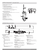
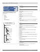
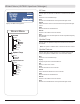

AXT630 Antenna Distribution System
Front and Rear Panel
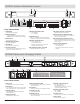
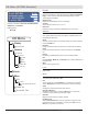
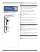
AXT900 Rackmount Charging Station
① LCD Display
Displays menu and settings.
② Navigation Buttons
• Arrows: Scroll menus and change settings
• SET: Enables menu edits and saves changes
③ Power Switch
Powers the unit on or off
④ AC Power Primary Switch
AC Main Power Switch
⑤ AC Power In
IEC Connector, 100-240 V AC
⑥ AC Power Cascade
Use the IEC extension cables to connect up to 5
devices to a single AC power source.
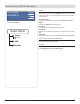
⑦ Network Speed LED (amber):
• Off = 10 Mbps
• On = 100 Mbps
⑧ Ethernet Ports (2)
PoE Class 1 enabled. Connect to an Ethernet
network to enable remote control and monitoring
⑨ Network status LED (green)
• Off = no network link
• On = network link active
• Flashing = network link active, flash rate
corresponds to traffic volume
⑩ RF Output Connectors, Channel B
Distributes RF signal for Channel B
⑪ RF Output Connectors, Channel A
Distributes RF signal for Channel A
⑫ Antenna IN Ports, Channels A and B
Antenna inputs are DC biased for use with active
antennas or in-line amplifiers.
⑬ RF Cascade Ports, Channels A and B
Passes the wideband RF signal from one device to
the next, allowing up to 5 devices to share a single
pair of antennas.
⑭ Antenna Input Status LED
• Green = DC power on
• Off = DC power off
• Red flashing = Antenna fault or over-current
condition
Front and Rear Panel
① LCD screen
Displays battery status and menu settings
② Control keys
For navigating the LCD screen. Press and hold
both arrow keys to enter or exit the utility menu.
③ Charging module
Interchangeable modules for handheld and
bodypack batteries.
④ Charge Status LED
Indicates battery charge status
⑤ Monitoring Selection LED
This white LED shows which battery is selected in
the monitoring menu.
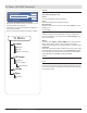
⑥ AC power in
Connect to AC mains with supplied power cable.
⑦ AC power cascade
Powers additional units.
⑧ Ethernet ports (2)
Connect to an Ethernet network to enable remote
control and monitoring.
⑨ Network status LED (green)
Off = No network link
On = Network link active
Flashing = Network link active, flash rate
corresponds to traffic volume.
⑩ Network speed LED (amber)
Off = 10 Mbps
On = 100 Mbps
⑪ Cooling fan vent
Clean fan screen as needed to maintain airflow.
⑫ Power switch
Powers the unit on and off.
152
Part 7: Reference Chapters
power
SET
2 3
1
AXT630
470-698 MHz
Antenna Distribution
Amplier
antenna
in
cascade
out
12.7V OUT
150 mA
B A
4
5 6
8
7 9
10 11
12
14
13
AXT630
Input 100-240 V ~ 50/60 Hz 0.8A max.
(5.8A max. outlet loaded)
Output 100-240~
5A max. 50/60 Hz UNSW.
4B 3B 2B 1B
RF outputs
4A 3A 2A 1A
RF outputs
PoE Class 1
① ② ③
④
⑤
Charger System
SET
AXT 900
AXT900
⑥
⑦ ⑨ ⑧ ⑩
⑪
⑫