
System information
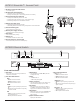
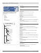
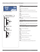

AXT200 Handheld Transmitter Menus and Navigation
The following menu descriptions reflect a linked AXT200 transmitter, with ShowLink remote control enabled and operated in Frequency
Diversity mode.
Menu Descriptions
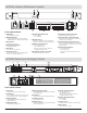
F1 Group and Channel
A group is a set of compatible
frequencies. A single frequency within a
group is a channel.
Use the SET key to select the group or
channel for F1.
• G: Change the group
• Ch: Change the channel
F1 Frequency
Manual frequency selection in 25 kHz
increments.
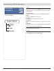
F2 Group and Channel
A group is a set of compatible
frequencies. A single frequency within a
group is a channel.
Use the SET key to select the group or
channel for F2.
Note: F2 can be turned off to operate the
transmitter in single carrier mode. Use the
SET key to highlight the ON or OFF option.
This function is available in the F2 frequency
menu and the F2 group and channel menu.
• ON: Frequency Diversity mode
• OFF: single carrier mode
F2 Frequency
Manual frequency selection in 25 kHz
increments.
Gain
Adjust the gain to set the input sensitivity
level. Gain range is -10 to +32 dB in 1 dB
steps.
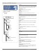
RF Mute
Disables the RF carrier signal, which
mutes transmission of audio.
• TX On: RF signal enabled
• TX Off: RF signal disabled
Unlink
Ends the Link relationship between
transmitter and receiver.
• YES: Ends the Link between transmitter
and receiver.
• NO: Preserves the Link between
transmitter and receiver.
Note: When a transmitter is unlinked, the
channel name reverts to Unlinked.
ShowLink Test
Activates the ShowLink test 5-bar
display. Measures the remote control
range of a ShowLink Access Point.
Note: A minimum of one bar must be dis-
played to have ShowLink control.
Firmware
Displays the installed firmware version.
Device ID
Identifies the transmitter on a linked
receiver or in WWB. Use the SET and
arrow keys to edit the Device ID.
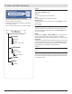
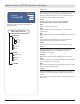
Locking the Buttons
Lock the buttons of the trans-
mitter to prevent accidental
or unauthorized parameter
changes.
Pressandholdthe▼and▲
buttons for 2 seconds to lock.
Repeat to unlock.
RF PWR
Sets RF power level. Access
this menu by pressing and
holding the SET button and
thenpressingthe▼button.
Use lower power settings to
conserve battery life and to
prevent RF overload at the
receiver.
Note: A password is required in
some regions to change the RF
power level.
Power-on RF mute
Power-on RF mute prevents
transmission of audio when
powering on the transmitter.
With the transmitter turned off,
pressandholdboththe▼but-
ton and the SET button, and
then press and hold the Power
button.
After power-on, an RF Muted
message indicates that the
transmitter is in RF Mute mode.
Note: RF Mute mode persists
through power cycles of the
transmitter.
PCB Serial Number
Displays the serial number of
the printed circuit board (PCB)
installed in the unit.
1. Enter the RF PWR menu
by pressing and holding the
SET button, and then press-
ingthe▼button.
2. Pressthe▲buttontoaccess
the serial number.
3. Momentarily press the power
button to return to the home
menu screen.
154
Part 7: Reference Chapters
6
<Unlinked>
F1: 525.725 MHz
F2: 585.625
}
|
6:15
F1 Group
and Channel
F2 Group
and Channel
F1 Frequency
F2 Frequency
Gain
RF Mute
Unlink
ShowLink Test
Firmware
Device ID
Home Screen