
System information


Gain and Attenuation
Use the RF Gain menu to maintain consistent signal levels sent to connected devices. The available adjustment range is
-12 to +3 dB when the Cascade ports are off and -15 to 0 dB when the cascade ports are active.
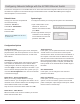
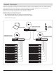
Connecting Devices to the RF Outputs
Connect an A and B pair of RF outputs from the Antenna
Distribution System to the A and B inputs of the device.
Input Band Filtering
Input band filters improve linearity of the system by rejecting out-of-band signals. Select the band filter that most closely
matches the tuning range of connected devices to optimize performance.
The Wideband setting passes 470-698 MHz (AXT630) or 606-814 MHz (AXT631).
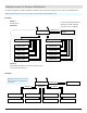
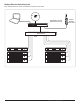
Adding an AXT600 Spectrum Manager to an
Antenna System
Connect the AXT600 Spectrum Manager to the RF
Cascade ports of an AXT630 or AXT631.
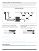
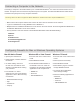
AXT630/AXT631 RF Output Distribution
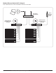
AXT630/AXT631 Signal Flow
The RF distribution ports of an AXT630 or AXT631 Antenna Distribution System send the signal from a pair of antennas
to up to 4 receivers or additional antenna distribution systems. Port-to-port isolation reduces interference, making the
distribution ports the best option for distributing signal to additional devices.
Note: The input band filters act on the RF distribution ports but do not affect the RF cascade ports.
52
Part 2: System Setup and Configuration
antenna
in
cascade
out
12.7V OUT
150 mA
B A
4B 3B 2B 1B
RF outputs
4A 3A 2A 1A
RF outputs
antenna
in
cascade
out
12.7V OUT
150 mA
B A
AXT630 or AXT631
Spectrum Manager
antenna
in
cascade
out
12.7V OUT
150 mA
B A
4B 3B 2B 1B
RF outputs
4A 3A 2A 1A
RF outputs
antenna
in
cascade
out
12.7V OUT
150 mA
B A
AXT630 or AXT631
(Cascade Bypass)
() Denotes gain when cascade is disabled
Passive Splitter
-5.0 dB0 dB
50
Ω 50 Ω
-15 dB to +0 dB
(-12 dB to +3 dB)
-15 dB to +0 dB
(-12 dB to +3 dB)
50
Ω
Passive Splitter
50
Ω
-15 dB to +0 dB
(-12 dB to +3 dB)
-15 dB to +0 dB
(-12 dB to +3 dB)
Passive Splitter
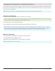
User Gain Adjust
50
Ω50 Ω
Antenna In Cascade Out Distro Out 1 Distro Out 4Distro Out 3Distro Out 2
Filter Select Switch
Filter Select Switch
Filter 4
Wide Band
Filter 3
Filter 2
Filter 1
Passive Splitter
AXT 630/ AXT631 Circuit Diagram
LNA