
System information

69
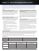
Chapter 12 ‒ ShowLink™ Network
Coverage Area
The coverage area of the access point is approximately the same as the transmitter’s UHF range (depending on the RF
squelch setting of the receiver). Use the ShowLink Test feature in the receiver menu to map the boundaries of the cover-
age area. Multiple access points can be used to increase the coverage area or to expand coverage to multiple rooms.
Transmitter Capacity
A single access point supports up to 16 Axient transmitters. Any transmitter within range of an active access point with
available capacity will be automatically controlled by that access point. When multiple access points are used to increase
transmitter capacity or to increase coverage range, transmitter control is automatically divided between each access point.
All changes in control between access points occur seamlessly and automatically, without requiring user intervention.
Transmitter Control
An access point with available capacity will automatically control linked transmitters that are within the coverage area.
Multiple access points automatically self-manage to divide transmitter control and maintain coverage. Transitions between
access point control do not affect the transmission of the audio channel.
2.4 GHz Channel Agility to Avoid Interference
When interference is present from Wi-Fi or other devices sharing the spectrum, built-in channel agility automatically
switches the access point and all controlled transmitters to a clear channel. Channel agility is able to avoid interference
from the following devices that operate in the 2.4 GHz spectrum:
• Wi-Fi (802.11)
• Cordless phones
• Wireless video
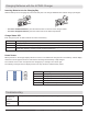
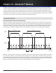
Use the following steps to set up a ShowLink network:
1. Connect the Ethernet cable: Connect an Ethernet cable to a Class 1 Power over Ethernet (PoE) port located on the
rear panel of Axient rack components. The PoE port supplies operating power and carries network communication for
the access point.
2. Perform an IR Sync to Link the transmitter and receiver: A Linking relationship must be established to allow the
transmitter to join the ShowLink network.
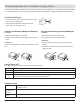
ShowLink Icon
The ShowLink icon appears on the home screens of a linked transmitter and receiver to indicate that the transmitter is
within range of an access point making remote control possible. If the transmitter is beyond the range of the access point,
or if the receiver is off-line, the icon will disappear, indicating a loss of ShowLink control.
Setting up a ShowLink Network
Note:IfaPoEenabledEthernetportisnotavailable,connecta15VDC∓10%(600mA)powersupplytotheexternalpowersupplyjackandconnect
a standard Cat. 5 Ethernet cable to the Ethernet port.