
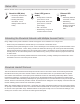
System information

71
Chapter 12 ‒ ShowLink™ Network
i
i
i
i
i
i
i
i
i
i
i
i
i
i
i
i
i
i
i
i
i
i
i
i
i
i
i
i
i
i
i
i
i
i
i
i
i
i
i
i
i
i
i
i
i
i
i
i
i
i
i
i
i
i
i
i
i
i
i
i
i
i
i
i
i
i
i
i
i
i
i
i
i
i
i
i
i
i
i
i
i
i
i
i
i
i
i
i
i
i
i
i
i
i
i
i
i
i
i
i
i
i
i
i
i
i
i
i
i
i
i
i
i
i
i
i
i
i
i
i
i
i
i
i
i
i
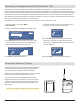
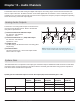
LEDs on the side of the access point housing indicate the flow of data traffic and the status of the access point.
ShowLink LED (blue)
• ON Steady: ShowLink OK,
no data transmission.
• Flashing: Data being
transmitted - rate of
flashing indicates level of
activity.
Power LED (green or
amber)
• Steady Green: Power ON;
power source = PoE
• Steady Amber: Power ON;
power source = external
power supply
• OFF = No Power
• Red Flashing = response to
remote ID flash command
Ethernet LED
(green)
• ON Steady: Ethernet
connected, no traffic
• ON Flashing:
Ethernet connected,
flashing corresponds
to volume of data
traffic.
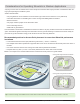
Using multiple access points extends the network and supports more transmitters over a larger area.
• Each access point added to the network adds up to 16 channels of transmitter control
• Positioning access points throughout a venue, such as backstage or near dressing rooms, provide transmitter control
for the entire performance – before, during, and after the talent takes the stage. The access points will automatically
manage the handoff of transmitters from one access point to another, extending the range of the ShowLink network.
Access points can be connected anywhere on the network as long as they are all on the same physical network and
IP subnet mask.
• The access points automatically maintain ShowLink communication, providing uninterrupted communication as the
transmitters move from one access point to another
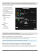
This section discusses the ShowLink handoff protocol and its affect on the remote control functions during the handoff.
Each ShowLink access point on the network contains a list of transmitters known as a permissions table. The permis-
sions table is formed when the access point queries networked receivers for valid linking relationships. When a linked
transmitter is powered on, it searches for an access point on the ShowLink network to associate with to enable remote
control. Transmitters with valid linking relationships are granted permission to associate with the access point and join the
network. Once the transmitter has joined the network, the ShowLink icon will appear on the displays of the transmitter and
receiver indicating remote control of the transmitter is possible.
When using multiple AXT610 Access Points, a transmitter may change association between several access points based
on capacity or location within the venue. If a transmitter loses association with an access point, it will automatically search
for the next access point within range. Handoffs between access points usually occur in a few seconds resulting in a mo-
mentary loss of remote control, but leave the audio signal uninterrupted.
Status LEDs
Extending the ShowLink Network with Multiple Access Points
ShowLink Handoff Protocol