
System information

Chapter 13 ‒ Audio Channels
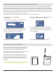
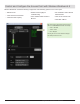
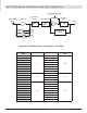
Analog Audio Outputs
The XLR and 1/4" analog audio outputs are located on the
rear panel of the AXT400 receiver. Refer to the AXT400
user guide for specifications.
① Transformer balanced XLR audio output
For channel 1 and channel 2
Impedance:<150Ω
② Transformer balanced 1/4" (TRS) audio output
For channel 1 and channel 2
Impedance:<50Ω
③ Line/Mic switch
The Mic setting is 30 dB less than the Line setting (XLR
outputs only)
④ Ground lift switch
Lifts the ground from pin 1 of the XLR output and the
sleeve of the 1/4" output
Note: In Frequency Diversity mode, the combined audio from
receivers 1 and 2 is routed to each of the analog output connectors.
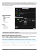
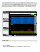
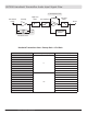
The table below offers a comparison of the output gain at the XLR output for AXT400 and UR4 receivers for each Shure
transmitter model. Use the information in the table to achieve consistent gain levels when using systems comprised of
both Axient series and UR series components.
Transmitter
AXT100
Bodypack
AXT200
Handheld
UR1
Bodypack
UR1M
Bodypack
UR2
Handheld
gain = 0 dB gain = 0 dB gain = 0 dB gain = 0 dB gain = 0 dB
sens = 0 dB sens = 0 dB
Receiver AXT400 +10 dB gain +15 dB gain +15 dB gain +15 dB gain +15 dB gain
audio output
level = 0 dB
UR4 N/A N/A +18 dB gain +18 dB gain +18 dB gain
System gain from transmitter input to receiver XLR output (line) when transmitter gain = 0 dB
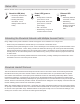
The AXT400 receiver offers both analog and digital audio outputs. For analog output, each receiver channel has XLR
and 1/4" output connectors. An AES3 connector carries 24-bit digital audio for channels 1 and 2. Connection ports are
available to sync the receiver with external word clock sources. Highly-linear frequency response and digital companding
ensure the accuracy of the audio output signals.
System Gain
78
Part 3: System Operation
3 4
1 2 1 2
3 4
analog outputs receiver 2
line
mic
lift
GND
analog outputs receiver 1
line
mic
lift
GND