
PORTABLE AUTOMATIC MIXER User Guide FP410


2
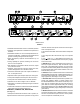
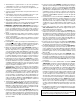
MODEL FP410
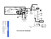
FIGURE 1
1
2
3
4
5
6
7
8
9
10
111
2
3
4
5
6
7
8
9
10
111
2
3
4
5
6
7
8
9
10
11
432
LINK
FP410
TAPE OUT
MIC LINE MIC LINE MIC LINE MIC LINE MIC LINE MIC LINEPHANTOM
OFF ON
OUT IN
MASTER
PULL FOR 1 KHZ TONE
BATTERY TEST MANUAL AUDIO LIMITER IN
PULL FOR MONITOR
OFF ON
PEAK
VU
100%
MONITOR IN
432 1
PHONES
1
1
2
3
4
5
6
7
8
9
10
11
1
2
3
4
5
6
7
8
9
10
11
-- 2 0 -- 1 0 -- 7 -- 5 -- 3 -- 2 -- 1 0 + 1 + 2 + 3
-- 2 4 -- 2 0 -- 1 6 -- 1 2 -- 8 -- 4 0 + 4 + 8 + 1 2 + 1 6
Selectable Off--Attenuation control for seamless operation
Automatic gain adjustment as additional microphones are
activated
Defeatable “Last MicLock--On” circuit keeps at least one mi-
crophone on at all times—maintains acoustic ambiance and
prevents confusing background sound changes
Wide, flat frequency response and low distortion up +18
dBm output
Linking capability for systems containing over 25 mixers
and over 100 microphones
LED indication of microphone channel mix levels, output
level, and limiter action
Automatic muting p revents annoying thumps and loud-
speaker damage when unit is turned on and off
Transformer--balanced inputs and outputs switchable to
line-- or microphone--level
Separate monitor input and tape output (aux--level) jacks
Front--panel headphone monitor jacks with level control
Front--panel auto--disable switch for manual operation
Operates from ac mains voltage or two 9 V batteries
Switchable 14 V and 48 V phantom powering for condenser
microphones
Underwriters Laboratories Listed and Canadian Standards
Association listed as Certified (FP410 only)
CONTROLS, CONNECTORS, INDICATORS
(See Figure 1)
1. Microphone Channel Gain Controls 1--4: At “0” position, mi-
crophone channel is removed from operation. Turning control
clockwise activates microphone channel and allows adjust-
ment of microphone level.
2. Input Normal Green LED: Should flicker with normal speech
levels.
3. Input High Red LED: Should flicker only on loud speech
peaks.
4. Flat (
)/Low--Cut ( ) Slide Switches: Provide low --fre-
quency rolloff to reduce undesirable low--frequency signals
such as wind noise.
5. MASTER Rotary Control: Determines the level of the com-
bined input signals at Mic/Line, Tape and Phones outputs.
PULL FOR 1 kHz TONE position activates 1 kHz tone oscilla-
tor (tone level is determined by Master control setting). Oscilla-
tor signal appears at all outputs. When oscillator is not in use,
knob should be pushed in.
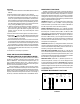
6. PEAK/VU Output Level Meter: Meter function is selected by
adjacent PEAK/VU slide switch. In PEAK s witch position, me-
ter indicates peak signal levels. In VU position, it indicates av-
erage signal levels, simulating a true VU meter.
7. BATTERY TEST Momentary Slide Switch: Operates in con-
junction with PEAK/VU Meter to indicate battery condi-
tion.With POWER switch on and switch in momentary--on po-
sition, new set of batteries lights all green LEDs. Number of
green LEDs lit indicates approximate battery life remaining
when alkaline batteries are used. NOTE: POWER LED begins
flashing when total battery supply voltage drops to 10 Vdc (one
green LED lit).
8. MANUAL/AUTO Slide Switch: Selects manual or automatic
microphone operating mode. In MANUAL position, unit oper-
ates as a conventional microphone mixer. In AUTO position,
unused microphones automatically turn off.