
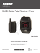
User's Manual


5
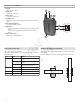
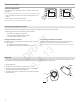
Guitar Pedal Receiver Overview
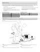
Display Screen, Indicators, and Controls
The controls and display offer specific functionality depending on which mode is selected:
① Power Switch
Turns power on or off.
② DC Power Connector
Connect DC power supply (9 to 15 V DC,
250 mA min.)
Note: Compatible with positive tip or negative tip
power supplies.
③ Audio Output Jack
Connect to amplifier or mixer.
Note: If using multiple effects pedals, place the
receiver pedal first in the signal chain.
④ USB Port
⑤ Display
Displays receiver and tuner settings.
⑥ Antenna
Carries wireless signal, 2 per receiver.
⑦ Footswitch
Press to select receiver or tuner mode.
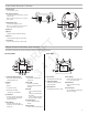
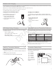
Tuner Mode
2 3
1
4
6
link
mode autoaudio rf channel
group
6
7
5
rf channel
group
auto
link
mode audio
1
3
4
5
6
2
7
8
9
rf channel
group
auto
link
mode audio
1
5
6
2
3
4
① Transmitter Battery Meter
Illuminated segments indicate
remaining battery life
② Display
Group
Channel
LK (controls locked)
UN (controls unlocked)
-- (frequency not available)
③ Link Button
Press to manually link receiver
to a transmitter or activate the
remote ID function
④ Mode Button
Press to enable audio gain
adjustment. Use ▲ ▼ buttons to
adjust gain.
⑤ Audio LED
Illumination corresponds to
audio level.
⑥ Auto LED
Illuminates if selected
group has backup channels
available.
⑦ RF LED
• ON = Linked transmitter
is on
• Flashing = Searching for
transmitter
• OFF = Linked transmitter
off or transmitter unlinked
⑧ Channel Button
Press to select and edit
channel
⑨ Group Button
Press to select and edit group
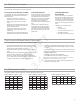
① Flat Indicator
Illuminates when note is flat.
② Tuning Bar Display
LEDs illuminate to indicate
tuning deviation.
③ Sharp Indicator
Illuminates when note is sharp.
④ Note Display
Displays the name of the note
or (--) if the tuner is idle.
⑤ Mode Button
Press to enter tuner menu
settings.
⑥ Arrow Buttons
Use ▲ ▼ buttons to select and
edit menu settings.
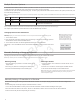
Receiver Mode
DRAFT
3.4.13