
User's Manual


Table Of Contents
- Table of Contents
- MX392 MX393Boundary Microphones
- General Description
- Interchangeable Cartridges
- Interchangeable Cartridges
- Permanent Installation
- Configuration
- Wiring Diagram
- Mute Button Configuration
- Connecting to an Automatic Mixer
- Logic Wiring
- Changing SWITCH OUT to Always Momentary
- Painting
- Specifications
- Furnished Accessories
- Certifications
Shure Incorporated
8/16
4.
5.
6.
7.
8.
9.
10.
11.
Remove cable from microphone housing.
Insert cable through access hole in microphone base.
Insert cable connector through hole and thread it into "L" bracket.
If desired, rubber strain relief can be reattached to cable end or removed from cable before fastening it to bracket.
Re-connect wires to proper screw terminals on circuit board.
Insert supplied round rubber plug into unused side cable exit.
Reinstall grille and foam screen.
Insert cable through hole in mounting surface. Secure microphone to mounting surface.
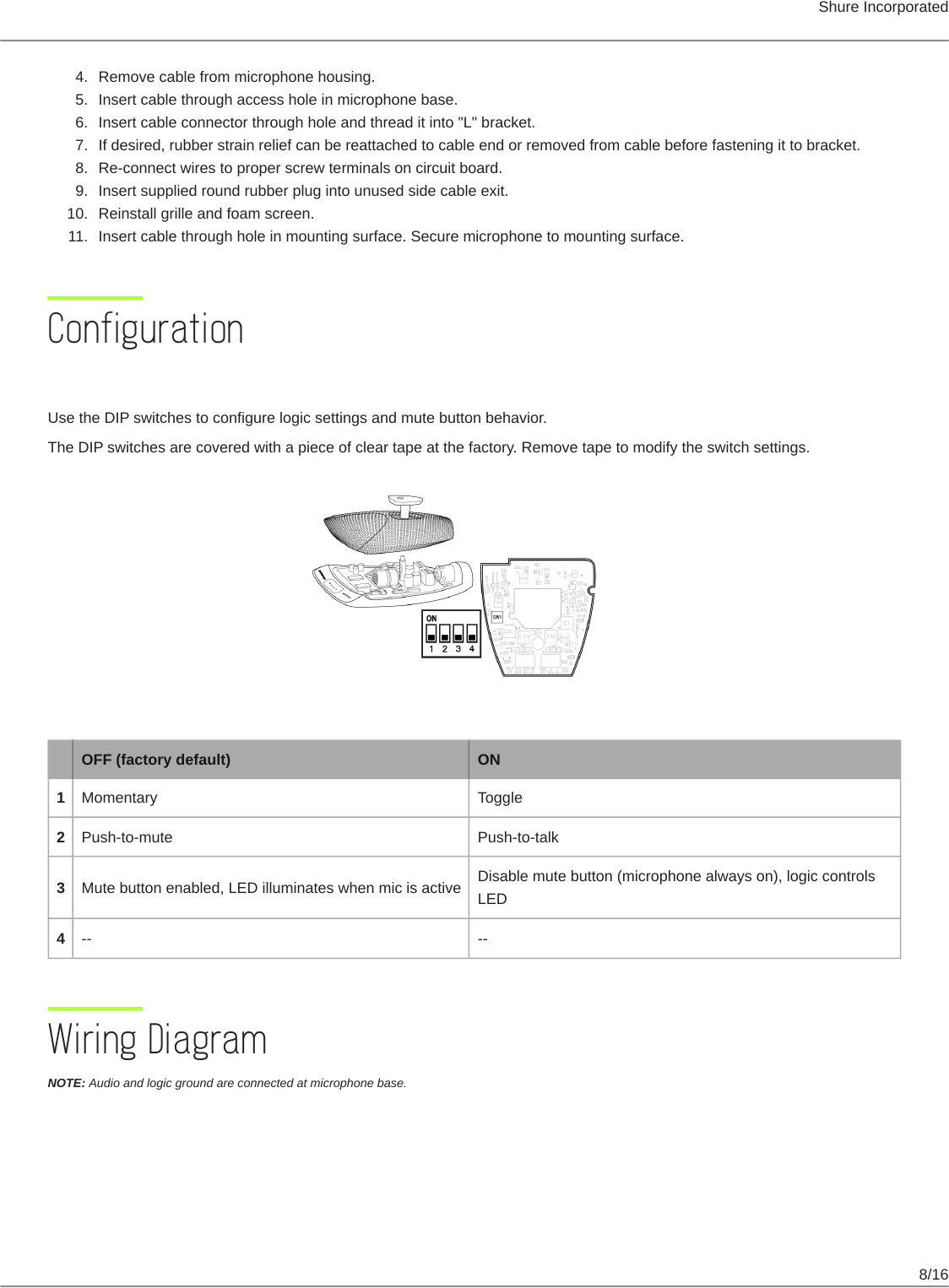
Configuration
DIP Switches
Use the DIP switches to configure logic settings and mute button behavior.
The DIP switches are covered with a piece of clear tape at the factory. Remove tape to modify the switch settings.
OFF (factory default) ON
1 Momentary Toggle
2 Push-to-mute Push-to-talk
3 Mute button enabled, LED illuminates when mic is active
Disable mute button (microphone always on), logic controls
LED
4 -- --
Wiring Diagram
NOTE: Audio and logic ground are connected at microphone base.